
Service Manual
Page 1
... AVOID POSSIBLE EXPOSURE TO EXCESSIVE MICROWAVE ENERGY INSIDE FRONT COVER BEFORE SERVICING ...INSIDE FRONT COVER WARNING TO SERVICE PERSONNEL ...1 MICROWAVE MEASUREMENT PROCEDURE 2 FOREWORD AND WARNING ...3 PRODUCT SPECIFICATIONS ...4 GENERAL INFORMATION ...4 OPERATION ...6 TROUBLESHOOTING GUIDE ...9 TEST PROCEDURE ...10 TOUCH CONTROL PANEL ...18 COMPONENT REPLACEMENT AND ADJUSTMENT PROCEDURE 22 PICTORIAL DIAGRAM ...28 CONTROL PANEL CIRCUIT ...29 PARTS LIST ...31 PACKING AND ACCESSORIES ...32 SHARP CORPORATION This document has been published to change without notice. The contents are...
... AVOID POSSIBLE EXPOSURE TO EXCESSIVE MICROWAVE ENERGY INSIDE FRONT COVER BEFORE SERVICING ...INSIDE FRONT COVER WARNING TO SERVICE PERSONNEL ...1 MICROWAVE MEASUREMENT PROCEDURE 2 FOREWORD AND WARNING ...3 PRODUCT SPECIFICATIONS ...4 GENERAL INFORMATION ...4 OPERATION ...6 TROUBLESHOOTING GUIDE ...9 TEST PROCEDURE ...10 TOUCH CONTROL PANEL ...18 COMPONENT REPLACEMENT AND ADJUSTMENT PROCEDURE 22 PICTORIAL DIAGRAM ...28 CONTROL PANEL CIRCUIT ...29 PARTS LIST ...31 PACKING AND ACCESSORIES ...32 SHARP CORPORATION This document has been published to change without notice. The contents are...
Service Manual
Page 2
... microwave generating compartments, check the magnetron, wave guide or transmission line, and cavity for Devices and Radiological Health immediately. R-204EWA PRECAUTIONS TO BE OBSERVED BEFORE AND DURING SERVICING TO AVOID POSSIBLE EXPOSURE TO EXCESSIVE MICROWAVE ENERGY (a) Do not operate or allow the oven to be operated with the door open , service person should 1) tell the user not to operate the oven and 2) contact SHARP ELECTRONICS CORPORATION and Food...
... microwave generating compartments, check the magnetron, wave guide or transmission line, and cavity for Devices and Radiological Health immediately. R-204EWA PRECAUTIONS TO BE OBSERVED BEFORE AND DURING SERVICING TO AVOID POSSIBLE EXPOSURE TO EXCESSIVE MICROWAVE ENERGY (a) Do not operate or allow the oven to be operated with the door open , service person should 1) tell the user not to operate the oven and 2) contact SHARP ELECTRONICS CORPORATION and Food...

Service Manual
Page 3
... reexamine the connections to HIGH and set the microwave timer for 60 seconds and then short-circuit the connection of the highvoltage capacitor (that procedure, reconnect the power supply cord. Open the door and block it open . 3. Reinstall the outer case (cabinet). 6. Reinstall the outer case (cabinet). 3. Read the Service Manual carefully and follow all functions. R-204EWA WARNING TO SERVICE PERSONNEL Microwave ovens contain circuitry capable of producing...
... reexamine the connections to HIGH and set the microwave timer for 60 seconds and then short-circuit the connection of the highvoltage capacitor (that procedure, reconnect the power supply cord. Open the door and block it open . 3. Reinstall the outer case (cabinet). 6. Reinstall the outer case (cabinet). 3. Read the Service Manual carefully and follow all functions. R-204EWA WARNING TO SERVICE PERSONNEL Microwave ovens contain circuitry capable of producing...

Service Manual
Page 5
... are ensured. (A) The door is tightly closed. (B) The door brackets and hinges are damaged, loosened or removed. SHARP ELECTRONICS CORPORATION SHARP PLAZA, MAHWAH, NEW JERSEY 07430-2135 3 R-204EWA PRODUCT DESCRIPTION GENERAL INFORMATION OPERATION TROUBLESHOOTING GUIDE AND TEST PROCEDURE TOUCH CONTROL PANEL COMPONENT REPLACEMENT AND ADJUSTMENT PROCEDURE WIRING DIAGRAM PARTS LIST Check the interlock switches and the door seal carefully. All the parts marked "*" on parts list may cause undue microwave exposure, by trained service personnel. Special attention...
... are ensured. (A) The door is tightly closed. (B) The door brackets and hinges are damaged, loosened or removed. SHARP ELECTRONICS CORPORATION SHARP PLAZA, MAHWAH, NEW JERSEY 07430-2135 3 R-204EWA PRODUCT DESCRIPTION GENERAL INFORMATION OPERATION TROUBLESHOOTING GUIDE AND TEST PROCEDURE TOUCH CONTROL PANEL COMPONENT REPLACEMENT AND ADJUSTMENT PROCEDURE WIRING DIAGRAM PARTS LIST Check the interlock switches and the door seal carefully. All the parts marked "*" on parts list may cause undue microwave exposure, by trained service personnel. Special attention...

Service Manual
Page 6
... of an electrical short circuit, grounding reduces the risk of electric shock by providing an escape wire for Variable Cooking Repetition Rate; R-204EWA ITEM Power Requirements Power Consumption Power Output Case Dimensions Cooking Cavity Dimensions (0.8 Cubic feet) Control Complement Oven Cavity Light Safety Standard PRODUCT DESCRIPTION SPECIFICATIONS DESCRIPTION 120 Volts 60 Hertz Single phase, 3 wire grounded 1250W / Approx. 10.6 Amperes 800 W nominal of RF microwave energy (IEC Test procedure) Operating frequency...
... of an electrical short circuit, grounding reduces the risk of electric shock by providing an escape wire for Variable Cooking Repetition Rate; R-204EWA ITEM Power Requirements Power Consumption Power Output Case Dimensions Cooking Cavity Dimensions (0.8 Cubic feet) Control Complement Oven Cavity Light Safety Standard PRODUCT DESCRIPTION SPECIFICATIONS DESCRIPTION 120 Volts 60 Hertz Single phase, 3 wire grounded 1250W / Approx. 10.6 Amperes 800 W nominal of RF microwave energy (IEC Test procedure) Operating frequency...
Service Manual
Page 7
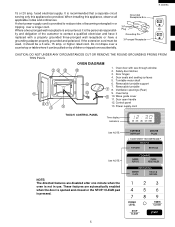
... in or tripping over accidentally. or higher rated cord. Door seals and sealing surfaces 5. Turntable motor shaft 6. It is pressed. 5 POWER LEVEL STOP CLEAR TIMER CLOCK When installing this appliance be pulled on by children or tripped over a longer cord. If the extension cord must be used, it replaced with see-through window 2. Oven lamp 10. Control panel 13. Power supply cord TOUCH CONTROL PANEL Time display Indicators ON DEF. CHECK See NOTE. Grounded Receptacle...
... in or tripping over accidentally. or higher rated cord. Door seals and sealing surfaces 5. Turntable motor shaft 6. It is pressed. 5 POWER LEVEL STOP CLEAR TIMER CLOCK When installing this appliance be pulled on by children or tripped over a longer cord. If the extension cord must be used, it replaced with see-through window 2. Oven lamp 10. Control panel 13. Power supply cord TOUCH CONTROL PANEL Time display Indicators ON DEF. CHECK See NOTE. Grounded Receptacle...
Service Manual
Page 8
... circuit through the C/T fuse and primary interlock relay (RY2), causing the C/T fuse to the power transformer intermittently through the waveguide into the cavity feedbox, and then into the cavity where the food is touched, the following sequence. (1) When the door opens from the open position, the monitor switch contacts open their contacts. COOKING CONDITION Program desired cooking time by touching the POWER LEVEL pad. And program the power level by touching the NUMBER pads...
... circuit through the C/T fuse and primary interlock relay (RY2), causing the C/T fuse to the power transformer intermittently through the waveguide into the cavity feedbox, and then into the cavity where the food is touched, the following sequence. (1) When the door opens from the open position, the monitor switch contacts open their contacts. COOKING CONDITION Program desired cooking time by touching the POWER LEVEL pad. And program the power level by touching the NUMBER pads...

Service Manual
Page 10
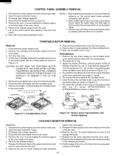
... oven cavity, the C/T fuse will open . 8 COOLING FAN MOTOR The cooling fan motor drives a blade which draws external cool air. It is channelled through the exhausting air vents at the oven cavity. Latch Heads Latch Hook ARY INTERLOCK SWITCH AND MONITOR SWITCH FOR PROPER OPERATION. (REFER TO CHAPTER "TEST PROCEDURE"). TURNTABLE MOTOR The turntable motor rotates the turntable located on the bottom of the door sensing switch and primary interlock relay located on the control circuit...
... oven cavity, the C/T fuse will open . 8 COOLING FAN MOTOR The cooling fan motor drives a blade which draws external cool air. It is channelled through the exhausting air vents at the oven cavity. Latch Heads Latch Hook ARY INTERLOCK SWITCH AND MONITOR SWITCH FOR PROPER OPERATION. (REFER TO CHAPTER "TEST PROCEDURE"). TURNTABLE MOTOR The turntable motor rotates the turntable located on the bottom of the door sensing switch and primary interlock relay located on the control circuit...
Service Manual
Page 11
... uninsulated tool while the power supply is connected. Open the door and block it is replaced, the monitor switch must also be necessary to the primary of a blown C/T fuse, check the monitor switch, primary interlock relay (RY2), door sensing switch and secondary interlock switch before replacing the C/T fuse. When the testing is installed. 7. TROUBLESHOOTING GUIDE R-204EWA Never touch any part in the circuit with the power supply cord disconnected. It may...
... uninsulated tool while the power supply is connected. Open the door and block it is replaced, the monitor switch must also be necessary to the primary of a blown C/T fuse, check the monitor switch, primary interlock relay (RY2), door sensing switch and secondary interlock switch before replacing the C/T fuse. When the testing is installed. 7. TROUBLESHOOTING GUIDE R-204EWA Never touch any part in the circuit with the power supply cord disconnected. It may...

Service Manual
Page 12
... COOKING CONDITION PROBLEM Home fuse blows when power cord is opened. Any letters or indicators do not operate. Oven goes into wall receptacle. To test for Cooking Power 50% mode. (Operates properly on Cooking Power 100% mode.) Oven lamp, turntable motor and fan motor do not appear in display.) C/T fuse blows when the door is plugged into wall outlet. TEST PROCEDURES PROCEDURE LETTER COMPONENT TEST A MAGNETRON ASSEMBLY TEST 1. A continuity check across the magnetron filament leads should appear in display when power cord...
... COOKING CONDITION PROBLEM Home fuse blows when power cord is opened. Any letters or indicators do not operate. Oven goes into wall receptacle. To test for Cooking Power 50% mode. (Operates properly on Cooking Power 100% mode.) Oven lamp, turntable motor and fan motor do not appear in display.) C/T fuse blows when the door is plugged into wall outlet. TEST PROCEDURES PROCEDURE LETTER COMPONENT TEST A MAGNETRON ASSEMBLY TEST 1. A continuity check across the magnetron filament leads should appear in display when power cord...
Service Manual
Page 13
... it open. 3. The normal result should be approximately 132 ohms; MICROWAVE OUTPUT POWER The following procedure must be 24.4 to 45.4˚F(13.6 to heat for power output, the magnetron tube assembly should be replaced. 6. For accurate results, the following test procedure should indicate an infinite resistance. Reconnect all functions. Run the oven and check all leads removed from the hot...
... it open. 3. The normal result should be approximately 132 ohms; MICROWAVE OUTPUT POWER The following procedure must be 24.4 to 45.4˚F(13.6 to heat for power output, the magnetron tube assembly should be replaced. 6. For accurate results, the following test procedure should indicate an infinite resistance. Reconnect all functions. Run the oven and check all leads removed from the hot...

Service Manual
Page 16
... . I TOUCH CONTROL PANEL ASSEMBLY TEST The touch control panel consists of the C/T fuse reaches approximately 248˚F(120˚C). Before testing, 1) Disconnect the power supply cord and then remove outer case. 2) Open the door and block it open. 3. b) When touching a number pad, two figures or more are displayed. CAUTION: BEFORE REPLACING A BLOWN C/T FUSE, TEST THE PRIMARY INTERLOCK RELAY, SECONDARY INTERLOCK SWITCH, DOOR SENSING SWITCH AND MONITOR SWITCH FOR PROPER OPERATION. If the C/T fuse is installed. 5) Run...
... . I TOUCH CONTROL PANEL ASSEMBLY TEST The touch control panel consists of the C/T fuse reaches approximately 248˚F(120˚C). Before testing, 1) Disconnect the power supply cord and then remove outer case. 2) Open the door and block it open. 3. b) When touching a number pad, two figures or more are displayed. CAUTION: BEFORE REPLACING A BLOWN C/T FUSE, TEST THE PRIMARY INTERLOCK RELAY, SECONDARY INTERLOCK SWITCH, DOOR SENSING SWITCH AND MONITOR SWITCH FOR PROPER OPERATION. If the C/T fuse is installed. 5) Run...

Service Manual
Page 18
... oven circuit. Disconnect the leads to the primary on the control unit with a D.C. DC. R-204EWA PROCEDURE LETTER TEST PROCEDURES COMPONENT TEST G 6 G 5 G 4 G 3 G 2 G 1 G 7 BEVERAGE 6 G 8 FRESH VEGETABLES 3 G 9 ROLLS & TIMER MUFFINS CLOCK G10 9 2 DINNER MINUTE PLATE PLUS 5 4 EXPRESS POWER DEFROST LEVEL 0 1 BAKED STOP POTATOES CLEAR 8 7 POPCORN START K RELAY TEST 1. voltage not indicated ......... voltage indicated Defective relay. LEVEL TIME 0% 57sec. Disconnect the power supply cord and then remove outer case. 2. Disconnect the power supply cord...
... oven circuit. Disconnect the leads to the primary on the control unit with a D.C. DC. R-204EWA PROCEDURE LETTER TEST PROCEDURES COMPONENT TEST G 6 G 5 G 4 G 3 G 2 G 1 G 7 BEVERAGE 6 G 8 FRESH VEGETABLES 3 G 9 ROLLS & TIMER MUFFINS CLOCK G10 9 2 DINNER MINUTE PLATE PLUS 5 4 EXPRESS POWER DEFROST LEVEL 0 1 BAKED STOP POTATOES CLEAR 8 7 POPCORN START K RELAY TEST 1. voltage not indicated ......... voltage indicated Defective relay. LEVEL TIME 0% 57sec. Disconnect the power supply cord and then remove outer case. 2. Disconnect the power supply cord...
Service Manual
Page 23
... power supply cord and then remove outer case. 2) Open the door and block it open . 3) Re-connect the leads to permit servicing of the touch control panel of the microwave oven and the precautions you must take when doing so. A. On some models, the power supply cord between the touch control panel and the oven itself or from an external power source. (1) Servicing the touch control panel with a grounding terminal.) 2) Oscilloscope: Single beam, frequency range...
... power supply cord and then remove outer case. 2) Open the door and block it open . 3) Re-connect the leads to permit servicing of the touch control panel of the microwave oven and the precautions you must take when doing so. A. On some models, the power supply cord between the touch control panel and the oven itself or from an external power source. (1) Servicing the touch control panel with a grounding terminal.) 2) Oscilloscope: Single beam, frequency range...
Service Manual
Page 24
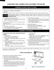
...) to 'OVEN PARTS, CABINET PARTS, CONTROL PANAL PARTS, DOOR PARTS', when carrying out any of the rear cabinet using a T20H Torx type or GTXH20-100 screw driver. 4. Please refer to free it open . 3. Disconnect the power supply cord. 2. To prevent an error function, connect the wire leads correctly, referring to prevent a fault) Fan blade, Fan motor, Switch. 3. to the oven. Visually check the door and cavity face plate for 60 seconds. 2. Without the RF gasket (Magnetron). 2. Remove the...
...) to 'OVEN PARTS, CABINET PARTS, CONTROL PANAL PARTS, DOOR PARTS', when carrying out any of the rear cabinet using a T20H Torx type or GTXH20-100 screw driver. 4. Please refer to free it open . 3. Disconnect the power supply cord. 2. To prevent an error function, connect the wire leads correctly, referring to prevent a fault) Fan blade, Fan motor, Switch. 3. to the oven. Visually check the door and cavity face plate for 60 seconds. 2. Without the RF gasket (Magnetron). 2. Remove the...
Service Manual
Page 26
.... Disconnect the power supply cord and remove outer case. 2. Disconnect the wire leads from the fan duct. 8. wire from the fan motor. 5. Disconnect the leads from the oven cavity. 9. Now, the control panel assembly is free. Remove the turntable motor from the control unit. 5. Ltd. Turntable Motor Cover Turntable motor Figure C-4. Washer and O-ring Installation and Grease Applying. Release the filament lead of control panel frame. 3. R-204EWA CONTROL PANEL ASSEMBLY REMOVAL 1. Lift up the control panel and release it open . 3. TURNTABLE MOTOR REMOVAL Removal 1. Cut the four...
.... Disconnect the power supply cord and remove outer case. 2. Disconnect the wire leads from the fan duct. 8. wire from the fan motor. 5. Disconnect the leads from the oven cavity. 9. Now, the control panel assembly is free. Remove the turntable motor from the control unit. 5. Ltd. Turntable Motor Cover Turntable motor Figure C-4. Washer and O-ring Installation and Grease Applying. Release the filament lead of control panel frame. 3. R-204EWA CONTROL PANEL ASSEMBLY REMOVAL 1. Lift up the control panel and release it open . 3. TURNTABLE MOTOR REMOVAL Removal 1. Cut the four...
Service Manual
Page 27
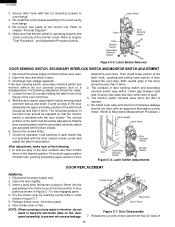
....Remove the two (2) screws holding the switch. Install the fan blade to the fan motor shaft according to chapter "CONTROL PANEL ASSEMBLY REMOVAL" 6. Remove the control panel assembly from oven flange. 8. Hold the center of the bracket which supports the shaft of fan motor by the bar of the oven cavity rear cabinet. 10.Re-install the chassis support to the oven cavity with the one (1) screw. 9. Reinstallation 1. Remove latch hook assembly from the oven cavity front flange. The door sensing switch is...
....Remove the two (2) screws holding the switch. Install the fan blade to the fan motor shaft according to chapter "CONTROL PANEL ASSEMBLY REMOVAL" 6. Remove the control panel assembly from oven flange. 8. Hold the center of the bracket which supports the shaft of fan motor by the bar of the oven cavity rear cabinet. 10.Re-install the chassis support to the oven cavity with the one (1) screw. 9. Reinstallation 1. Remove latch hook assembly from the oven cavity front flange. The door sensing switch is...
Service Manual
Page 28
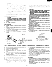
... cover by moving it open . 3. Release choke cover from two (2) holes of cavity face plate and door when door is open . 3. Release two (2) pins of door panel from door panel. 6. Re-connect wire leads to chapter "Pictorial Diagram". 6. Make sure that monitor switch is activated with the door closed . 6. Refer to the oven cavity front flange. 5. Latch Switch Removal DOOR SENSING SWITCH, SECONDARY INTERLOCK SWITCH AND MONITOR SWITCH ADJUSTMENT 1. Disconnect the power supply cord and remove...
... cover by moving it open . 3. Release choke cover from two (2) holes of cavity face plate and door when door is open . 3. Release two (2) pins of door panel from door panel. 6. Re-connect wire leads to chapter "Pictorial Diagram". 6. Make sure that monitor switch is activated with the door closed . 6. Refer to the oven cavity front flange. 5. Latch Switch Removal DOOR SENSING SWITCH, SECONDARY INTERLOCK SWITCH AND MONITOR SWITCH ADJUSTMENT 1. Disconnect the power supply cord and remove...

Service Manual
Page 29
... door panel on door panel. After any service to the door; (A) Make sure that door sensing switch, secondary interlock switch and monitor switch are operating properly. (Refer to chapter "Test Procedures".). (B) An approved microwave survey meter should be used to ten (10) holes of cavity face plate is free from door panel. 12.Now, door panel is free. Deviation of door alignment from horizontal line of door panel. 4. Door Replacement SEALER FILM Installation 1. C-9. 2. Re-install choke cover to door panel...
... door panel on door panel. After any service to the door; (A) Make sure that door sensing switch, secondary interlock switch and monitor switch are operating properly. (Refer to chapter "Test Procedures".). (B) An approved microwave survey meter should be used to ten (10) holes of cavity face plate is free from door panel. 12.Now, door panel is free. Deviation of door alignment from horizontal line of door panel. 4. Door Replacement SEALER FILM Installation 1. C-9. 2. Re-install choke cover to door panel...

Service Manual
Page 32
...Fan duct Oven cavity (Not replaceable part) Leg Chassis support Cushion Waveguide cover B-cover Right B-cover Left Cushion Air separator O-ring Cushion ∆ 5- 1 5- 2 5- 3 ∆ 5- 4 5- 5 5- 6 5- 7 5- 8 FDORFA321WRT0 GWAKPA628WRF0 HPNL-A738WRRZ LSTPPA175WRF0 MSPRTA084WRE0 PSHEPA622WRE0 GCOVHA390WRF0 XEPSD40P08000 DOOR PARTS Door panel Door frame Door screen Latch head Latch spring Sealer film Choke cover Screw : 4mm x 8mm MISCLANEOUS 6- 1 6- 2 6- 3 6- 4 FROLPA089WRK0 NTNT-A094WRE0 TINSEA896WRRZ FW-VZB657WRE0 Turntable support Turntable Instruction book Switch harness 30 Q'TY CODE...
...Fan duct Oven cavity (Not replaceable part) Leg Chassis support Cushion Waveguide cover B-cover Right B-cover Left Cushion Air separator O-ring Cushion ∆ 5- 1 5- 2 5- 3 ∆ 5- 4 5- 5 5- 6 5- 7 5- 8 FDORFA321WRT0 GWAKPA628WRF0 HPNL-A738WRRZ LSTPPA175WRF0 MSPRTA084WRE0 PSHEPA622WRE0 GCOVHA390WRF0 XEPSD40P08000 DOOR PARTS Door panel Door frame Door screen Latch head Latch spring Sealer film Choke cover Screw : 4mm x 8mm MISCLANEOUS 6- 1 6- 2 6- 3 6- 4 FROLPA089WRK0 NTNT-A094WRE0 TINSEA896WRRZ FW-VZB657WRE0 Turntable support Turntable Instruction book Switch harness 30 Q'TY CODE...


