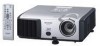
PG-F312X, PG-F262X, PG-F212X Operation Manual
Page 2
IMPORTANT • For your assistance in reporting the loss or theft of your Projector, please record the Model and Serial Number located on the bottom of the projector and retain this information. • Before recycling the packaging, please ensure that you have checked the contents of the carton thoroughly against the list of "Supplied accessories" on page 10. Model No.: Serial No.: ii
PG-F312X, PG-F262X, PG-F212X Operation Manual
Page 5
...manual carefully. ONLY 1 U.S.A. Do not stare into the beam of your purchase. 2. CAUTION RISK OF ELECTRIC SHOCK. The lightning flash with the projector. 1. DO NOT REMOVE SCREWS EXCEPT SPECIFIED USER SERVICE SCREW. REFER SERVICING TO QUALIFIED SERVICE PERSONNEL. Introduction Before using the REGISTRATION CARD packed with arrowhead..., or recall that you immediately receive the full benefit of sufficient magnitude to constitute a risk or electric shock to your new SHARP Projector, using the projector, please read this product to rain or moisture.
PG-F312X, PG-F262X, PG-F212X Operation Manual
Page 6
... to radio communications. This will be used in accordance with the device. The cable is likely to take adequate measures. This SHARP projector uses a DLP® chip. ONLY Caution Concerning Lamp Replacement See "Replacing the Lamp" on the picture screen. This unit has some inactive ... equipment such as large screen TVs, video systems and video cameras, there are designed to correct the interference at 1-800-BE-SHARP. ONLY WARNING: This is operated in a residential area is provided to ensure that the equipment must be required to provide reasonable...
PG-F312X, PG-F262X, PG-F212X Operation Manual
Page 7
... Maintenance P. 49 Troubleshooting PP. 64 and 65 Index P. 69 3 Example: "Picture" screen menu for setting up and operating the projector. ADJ Help Picture Mode Contrast Bright Red Blue CLR Temp BrilliantColorTM C.M.S. Introduction How to adjust. ADJ PRJ - MENU/HELP button Buttons ...used in the same manner. • In this operation manual, the illustration and the screen display are slightly different, depending on the projector. 1 Press MENU/HELP. • The "Picture" menu screen for using the buttons on the model. Note .........Indicates additional information ...
PG-F312X, PG-F262X, PG-F212X Operation Manual
Page 8
... the Background Image ........ 44 Selecting the Setup Guide 44 Reversing/Inverting Projected Images 44 Selecting the On-screen Display Language 44 Adjusting the Projector Function ("PRJ - ADJ" Menu 45 Auto Sync (Auto Sync Adjustment) ..... 45 Auto Power Off Function 45 Auto Restart Function 45 ...View 12 Inserting the Batteries 14 Usable Range 15 Quick Start Quick Start 16 Setup and Projection 16 Setup Setting up the Projector 18 Setting up the Projector 18 Standard Setup (Front Projection) ....... 18 Ceiling-mount Setup 18 Projection (PRJ) Mode 19 Screen Size and Projection ...
PG-F312X, PG-F262X, PG-F212X Operation Manual
Page 9
Introduction Troubleshooting with the "Help" Menu 48 Utilizing the "Help" Menu Functions .... 48 Reference Appendix Maintenance 49 Maintenance Indicators 50 Regarding the Lamp 52 Lamp 52 Caution Concerning the Lamp 52 Replacing the Lamp 52 Removing and Installing the Lamp Unit 53 Resetting the Lamp Timer 54 Storing the Projector 55 How to Use the Storage Case 55 Connecting Pin Assignments 56 RS-232C Specifications and Commands 58 Computer Compatibility Chart 63 Troubleshooting 64 For SHARP Assistance 66 Specifications 67 Dimensions 68 Index 69 5
PG-F312X, PG-F262X, PG-F212X Operation Manual
Page 12
... exhaust and intake vents. ■ Allow at least 11 13/16 inches (30 cm) of the projector ■ For minimal servicing and to maintain high image quality, SHARP recommends that it is from the wall outlet and wait at altitudes of lamp rupture, contact your eyes occasionally...When you use in direct sunlight or room light. Avoid locations with thin air, set up the projector in an area free from humidity, dust and cigarette smoke. Rest your nearest Sharp Authorized Projector Dealer or Service Center for a while. Caution concerning the lamp unit ■ Potential hazard of...
PG-F312X, PG-F262X, PG-F212X Operation Manual
Page 13
... click the pdf file to access the pro- Doing so may still be opened by holding the lens. ■ When storing the projector, ensure you are using the projector in. Other connected equipment ■ When connecting a computer or other cables connected to it. ■ If the power cord is unplugged...Open" menu. 9 To utilize these manuals, you unplug the power cord from the Internet (http://www.adobe.com). Introduction Caution regarding usage of the projector ■ If you are not to use an appropriate power cord for the country you want to view. 6 Double click the language (name of ...
PG-F312X, PG-F262X, PG-F212X Operation Manual
Page 14
... U.S.A. Optional accessories ■ Lamp unit ■ Ceiling-mount adaptor ■ Ceiling-mount unit ■ Remote receiver ■ 3 RCA to the wall outlet in your nearest Sharp Authorized Projector Dealer or Service Center. 10 Singapore Zealand and Oceania (6' (1.8 m)) (6' (1.8 m)) (6' (1.8 m)) (6' (1.8 m)) * Use the power cord that corresponds to mini D-sub 15 pin cable (10n (3.0 m)) AN-F212LP...
PG-F312X, PG-F262X, PG-F212X Operation Manual
Page 15
Introduction Part Names and Functions Numbers in this operation manual where the topic is explained. Projector Top View Power indicator 25, 50 STANDBY/ON 25 button For turning the power on the menu. Remote control 15 sensor Exhaust vent 49 25, ... Correction mode. Front View Zoom ring 26 For enlarging/ reducing the picture. ENTER button For setting 38 items selected or adjusted on and putting the projector into standby mode.
PG-F312X, PG-F262X, PG-F212X Operation Manual
Page 16
...27 adjustment foot 24 AC socket Connect the supplied power cord. Kensington Security Standard connector Using the Kensington Lock • This projector has a Kensington Security Standard connector for 22 DVI digital, computer RGB and component signals. Refer to the information that came... 22 S-VIDEO input terminal Terminal for connecting video equipment with an S-video terminal. 24 RS-232C terminal Terminal for controlling the projector using the supplied remote control as the computer mouse. 23 AUDIO 2 input terminal 22 VIDEO input terminal Terminal for instructions on ...
PG-F312X, PG-F262X, PG-F212X Operation Manual
Page 17
... image. BREAK TIMER button 32 For displaying the break time. KEYSTONE button 28 For entering the Keystone Correction mode. STANDBY button 25 For putting the projector into the standby mode. POINTER button 32 For displaying the pointer. AUTO SYNC button 33 For automatically adjusting images when connected to the respective input...
PG-F312X, PG-F262X, PG-F212X Operation Manual
Page 18
... batteries from the remote control if you wipe them first and then remove them using the remote control for a long time. • Comply with this projector may cause them to replace them as soon as leaving them in place.
PG-F312X, PG-F262X, PG-F212X Operation Manual
Page 19
When using the remote control • Ensure that you do not drop it or expose it to control the projector within the ranges shown in the illustration. In this case, move the projector away from the remote control can be reflected off a screen for easy operation. How- 30° ever, the effective distance...
PG-F312X, PG-F262X, PG-F212X Operation Manual
Page 20
...KEYSTONE button 1. Remove the lens cap and turn the projector on On the projector On the remote control _P. 25 16 Place the projector facing a wall or a screen _P. 18 2. Quick Start This section shows the basic operation (projector connecting with the computer). Setup and Projection In this ...section, connection of the projector When connecting equipment other than a computer, see the page described below for each step. For details,...
PG-F312X, PG-F262X, PG-F212X Operation Manual
Page 21
... INPUT mode Select the "COMPUTER" using Keystone Correction. On the On the remote projector control On-screen display _P. 25 17 Adjust the projected image with the Setup Guide 1 After the projector turns on the remote control, and then press the button again while the confirmation ...angle) and picture size, press ENTER to switch the INPUT mode. _P. 29 7. On the projector Shrinks upper side. Shrinks lower side. On the remote control _P. 28 6. On the On the remote projector control INPUT list INPUT COMPUTER D DVI-D Computer On-screen display (RGB) COMPUTER RGB 1024 ×...
PG-F312X, PG-F262X, PG-F212X Operation Manual
Page 22
...; Refer to page 20 for this installation. Before mounting the projector, contact your nearest Sharp Authorized Projector Dealer or Service Center to the screen with the projector's feet flat and level. Setting up the Projector Setting up the Projector For optimal image quality, position the projector perpendicular to obtain the recommended ceiling-mount adaptor and unit (sold...
PG-F312X, PG-F262X, PG-F212X Operation Manual
Page 23
... mounted, rear projection (with a translucent screen) [Menu item ➞ "Ceiling + Rear"] Indication of the 4 projection modes shown in the diagram below. Projection (PRJ) Mode The projector can set the PRJ mode in "SCR-ADJ" menu.
PG-F312X, PG-F262X, PG-F212X Operation Manual
Page 24
... the lens center to the bottom of the image (cm/in) S: Adjustable range of error in the values in ) See page 43. Setting up the Projector (Continued) Screen Size and Projection Distance NORMAL Mode (4:3) Picture (Screen) size Projection distance [L] Diag. [χ] Width Height Minimum [L1] Maximum [L2] 300Љ (762 cm...
PG-F312X, PG-F262X, PG-F212X Operation Manual
Page 25
After making all the connections are using a SHARP notebook computer). Terminals on the Projector Connections Equipment Computer Terminal on connected equipment Cable RGB output terminal RGB cable (supplied) Terminal on the projector COMPUTER/ COMPONENT RGB output terminal mini D-sub 15 pin to enable your near- Press "Fn" and "...F5" keys simultaneously when using , an image may not be turned on after all connections, turn on the projector and then the other cables or connectors not listed below. IMPORTANT: Ensure that the appropriate input mode has been selected on the...