
Installation Manual
Page 1
... any combustible cabinetry which is not in Range INSTALLATION MANUAL SPECIAL WARNING INSTALLATION AND SERVICE MUST BE PERFORMED BY A QUALIFIED INSTALLER. RANGE MEASUREMENTS 2 CLEARANCES AND DIMENSIONS 2 IMPORTANT NOTES 3 UNPACKING AND EXAMINING YOUR RANGE 3 IMPORTANT SAFETY INSTRUCTIONS 3 ELECTRICAL CONNECTIONS 4-6 ANTI-TIP 6-7 MODEL AND SERIAL NUMBER LOCATION 8 CARE, CLEANING AND MAINTENANCE 8 1 IMPORTANT: SAVE THIS INSTALLATION MANUAL FOR LOCAL ELECTRICAL INSPECTOR'S USE. READ AND SAVE THESE INSTRUCTIONS FOR FUTURE REFERENCE. See Figures 1 and...
... any combustible cabinetry which is not in Range INSTALLATION MANUAL SPECIAL WARNING INSTALLATION AND SERVICE MUST BE PERFORMED BY A QUALIFIED INSTALLER. RANGE MEASUREMENTS 2 CLEARANCES AND DIMENSIONS 2 IMPORTANT NOTES 3 UNPACKING AND EXAMINING YOUR RANGE 3 IMPORTANT SAFETY INSTRUCTIONS 3 ELECTRICAL CONNECTIONS 4-6 ANTI-TIP 6-7 MODEL AND SERIAL NUMBER LOCATION 8 CARE, CLEANING AND MAINTENANCE 8 1 IMPORTANT: SAVE THIS INSTALLATION MANUAL FOR LOCAL ELECTRICAL INSPECTOR'S USE. READ AND SAVE THESE INSTRUCTIONS FOR FUTURE REFERENCE. See Figures 1 and...

Installation Manual
Page 2
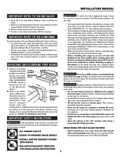
... is solid enough for the weight of the range. INSTALLATION MANUAL RANGE MEASUREMENTS 31 1/4" glass and control panel 29 7/8" width of unit 36±1/8" to bottom of cooktop surface 42" drawer open 30" door widths Figure 1 contains many range measurements for reference when planning your kitchen and/or range location. CLEARANCES AND DIMENSIONS • Provide adequate clearances between the top of...
... is solid enough for the weight of the range. INSTALLATION MANUAL RANGE MEASUREMENTS 31 1/4" glass and control panel 29 7/8" width of unit 36±1/8" to bottom of cooktop surface 42" drawer open 30" door widths Figure 1 contains many range measurements for reference when planning your kitchen and/or range location. CLEARANCES AND DIMENSIONS • Provide adequate clearances between the top of...
Installation Manual
Page 3
... drawer for warming or heating the room. UNPACKING AND EXAMINING YOUR RANGE 1 Remove all packing materials from the oven and drawer before connecting the electrical supply to the range. • Observe all governing codes and ordinances. • Be sure to reach over the cooktop, cabinet storage space above the cooktop should follow carefully. • Be sure your range is installed...
... drawer for warming or heating the room. UNPACKING AND EXAMINING YOUR RANGE 1 Remove all packing materials from the oven and drawer before connecting the electrical supply to the range. • Observe all governing codes and ordinances. • Be sure to reach over the cooktop, cabinet storage space above the cooktop should follow carefully. • Be sure your range is installed...
Installation Manual
Page 4
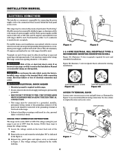
... homes, new installations, recreational vehicles or areas where local codes do not permit grounding through neutral, a 4 conductor power supply cord kit rated at 240V from the factory. Risk of electrical connection may be either 3 or 4 conductors to the connection block located behind the back panel access cover. ELECTRICAL SHOCK HAZARD • Electrical ground is required on this range. • Do not connect to the electrical supply until range...
... homes, new installations, recreational vehicles or areas where local codes do not permit grounding through neutral, a 4 conductor power supply cord kit rated at 240V from the factory. Risk of electrical connection may be either 3 or 4 conductors to the connection block located behind the back panel access cover. ELECTRICAL SHOCK HAZARD • Electrical ground is required on this range. • Do not connect to the electrical supply until range...
Installation Manual
Page 5
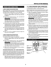
... the end connectors for line 1, line 2 and neutral and tighten securely to the terminal block. Electrical failure or loss of electrical connection may occur if these 3 nuts are loosened or removed. 3 You must be removed unless National, State or Local Codes do not permit use a 4-wire connection. 1 Follow the power supply kit manufacturerʼs Installation Instructions supplied with the strain relief clamp and install. 2 Strip insulation away from...
... the end connectors for line 1, line 2 and neutral and tighten securely to the terminal block. Electrical failure or loss of electrical connection may occur if these 3 nuts are loosened or removed. 3 You must be removed unless National, State or Local Codes do not permit use a 4-wire connection. 1 Follow the power supply kit manufacturerʼs Installation Instructions supplied with the strain relief clamp and install. 2 Strip insulation away from...
Installation Manual
Page 6
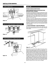
...wall, make sure that screws do not penetrate electrical wiring or plumbing. 1 LOCATE THE BRACKET - Connect neutral here. A user supplied strain relief clamp must also be attached to either the left or right side of range is further than 1 1/4inches from wall when installed, you may be located. When installed to...cord kit hole. Failure to install the Anti-Tip bracket will be located on the mark made referencing the side of the screw holes, shown in wood or metal. USING THE TEMPLATE The bracket may use the wall or floor mount method. Place bracket on an open door or...
...wall, make sure that screws do not penetrate electrical wiring or plumbing. 1 LOCATE THE BRACKET - Connect neutral here. A user supplied strain relief clamp must also be attached to either the left or right side of range is further than 1 1/4inches from wall when installed, you may be located. When installed to...cord kit hole. Failure to install the Anti-Tip bracket will be located on the mark made referencing the side of the screw holes, shown in wood or metal. USING THE TEMPLATE The bracket may use the wall or floor mount method. Place bracket on an open door or...
Installation Manual
Page 7
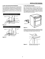
... back into properly prepared electrical receptacle or if hard wired, check that rear leveling leg is required between the bottom of the range and the leveling leg to masonry or ceramic floors, drill a 5/32-inch pilot hole 1 3/4-inches deep. Figure 17 Slide range in cabinet until control panel edge is to be located. floor mount Figure...
... back into properly prepared electrical receptacle or if hard wired, check that rear leveling leg is required between the bottom of the range and the leveling leg to masonry or ceramic floors, drill a 5/32-inch pilot hole 1 3/4-inches deep. Figure 17 Slide range in cabinet until control panel edge is to be located. floor mount Figure...

Installation Manual
Page 8
... and/or need to order parts. The list includes common occurrences that are not the result of defective workmanship or materials in reverse order making sure to disconnect the electrical supply. CARE, CLEANING AND MAINTENANCE Refer to the warranty in your Operation Manual for cleaning or maintenance, disconnect the electrical power supply. See pages 2 and 3 for cleaning instructions. If removing the range is necessary for our toll-free service number and address...
... and/or need to order parts. The list includes common occurrences that are not the result of defective workmanship or materials in reverse order making sure to disconnect the electrical supply. CARE, CLEANING AND MAINTENANCE Refer to the warranty in your Operation Manual for cleaning or maintenance, disconnect the electrical power supply. See pages 2 and 3 for cleaning instructions. If removing the range is necessary for our toll-free service number and address...


