
Service Manual
Page 1
... used for after sales service only. AF-05CML SERVICE MANUAL S3209AF05CML/ AIR CONDITIONER MODEL AF-05CML In the interests of user-safety (Required by safety regulations in some countries) the set should be restored to its original condition and only parts identical to those specified should be used . TABLE OF CONTENTS Page SPECIFICATIONS ...2 EWIRING DIAGRAM ...3 EXTERNAL DIMENSIONS ...3 HOW TO OPERATE ...4 INSTALLATIOIN INSTRUCTIONS ...5 DISASSEMBLING PROCEDURE ...7 HOW TO REPAIR REFRIGERATION ...10 ELECTRICAL COMPONENT TEST ...12 TROUBLESHOOTING GUIDE ...13 COOLING...
... used for after sales service only. AF-05CML SERVICE MANUAL S3209AF05CML/ AIR CONDITIONER MODEL AF-05CML In the interests of user-safety (Required by safety regulations in some countries) the set should be restored to its original condition and only parts identical to those specified should be used . TABLE OF CONTENTS Page SPECIFICATIONS ...2 EWIRING DIAGRAM ...3 EXTERNAL DIMENSIONS ...3 HOW TO OPERATE ...4 INSTALLATIOIN INSTRUCTIONS ...5 DISASSEMBLING PROCEDURE ...7 HOW TO REPAIR REFRIGERATION ...10 ELECTRICAL COMPONENT TEST ...12 TROUBLESHOOTING GUIDE ...13 COOLING...
Service Manual
Page 2
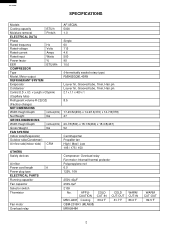
x I.D. x Length x Q'ty(mm) (Capillary tube) Refrigerant volume R-22(OZ) (Factory change) NET DIMENSIONS Width Height Depth inches(mm) Net Weight lbs GROSS DIMENSIONS Width Height Depth inches(mm) Gross Weight lbs FAN SYSTEM Indoor side(Evaporator) Outdoor side(Condenser) Air flow rate(indoor side) CFM OTHERS Safety devices Air filter Power cord length ft Power plug type ELECTRICAL PARTS Running capacitor Fan capacitor Selector switch Thermistor Fan motor Overload relay AF-05CML 5000 1.0 Single 60 115 4.6 500 95 10.0 (Hermetically...
x I.D. x Length x Q'ty(mm) (Capillary tube) Refrigerant volume R-22(OZ) (Factory change) NET DIMENSIONS Width Height Depth inches(mm) Net Weight lbs GROSS DIMENSIONS Width Height Depth inches(mm) Gross Weight lbs FAN SYSTEM Indoor side(Evaporator) Outdoor side(Condenser) Air flow rate(indoor side) CFM OTHERS Safety devices Air filter Power cord length ft Power plug type ELECTRICAL PARTS Running capacitor Fan capacitor Selector switch Thermistor Fan motor Overload relay AF-05CML 5000 1.0 Single 60 115 4.6 500 95 10.0 (Hermetically...

Service Manual
Page 3
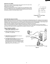
...-COOL MED-COOL HIGH-COOL RIBBED OVERLOAD RELAY THERMOSTAT 8 642 RE OR WH BK BK BK BL BK C R COMPRESSOR MOTOR GR S CONNECTOR 3 6 5 4 1 2 GR RE OR WH BL BK FAN MOTOR THERMAL H M L CAPACITOR 250V 6µF PROTECTOR RE WH RUNNING CAPACITOR GR 250V 40µF G EARTH M.C A.C BK BL FAN MOTOR Figure W-1 EXTERNAL DIMENSIONS AF-05CML 1-15/32" 13-5/8" 15-11/16" 17-23/32" 33-7/16" (full opened...
...-COOL MED-COOL HIGH-COOL RIBBED OVERLOAD RELAY THERMOSTAT 8 642 RE OR WH BK BK BK BL BK C R COMPRESSOR MOTOR GR S CONNECTOR 3 6 5 4 1 2 GR RE OR WH BL BK FAN MOTOR THERMAL H M L CAPACITOR 250V 6µF PROTECTOR RE WH RUNNING CAPACITOR GR 250V 40µF G EARTH M.C A.C BK BL FAN MOTOR Figure W-1 EXTERNAL DIMENSIONS AF-05CML 1-15/32" 13-5/8" 15-11/16" 17-23/32" 33-7/16" (full opened...
Service Manual
Page 4
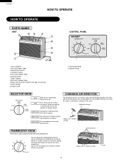
... Adjusts LEFT / RIGHT air flow. FAN This setting can adjust the cooling performance of the room. Lever 4 HIGH COOL Fan and cooling at medium. MED COOL Fan operates at medium speed. Horizontal louvers Adjusts UP / DOWN air flow. The lower the number, the warmer the room temperature. You will operate at medium speed; The fan will need to experiment to remove.) 0 Filter Handle q Power Cord CONTROL PANEL THERMOSTAT 5 4 6 7 SELECTOR LOW COOL FAN MED COOL 3 8 OFF 2 9 HIGH COOL 1 10 COOLER...
... Adjusts LEFT / RIGHT air flow. FAN This setting can adjust the cooling performance of the room. Lever 4 HIGH COOL Fan and cooling at medium. MED COOL Fan operates at medium speed. Horizontal louvers Adjusts UP / DOWN air flow. The lower the number, the warmer the room temperature. You will operate at medium speed; The fan will need to experiment to remove.) 0 Filter Handle q Power Cord CONTROL PANEL THERMOSTAT 5 4 6 7 SELECTOR LOW COOL FAN MED COOL 3 8 OFF 2 9 HIGH COOL 1 10 COOLER...
Service Manual
Page 5
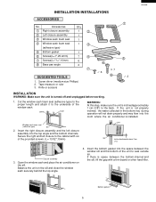
... unit to the cabinet with a thin board or other hard filler. Bottom gasket 5 Open the window sash and place the air conditioner on the sill and close the window sash securely behind the top angle. 4. If there is turned off and unplugged before working. 1. Accessories Q'ty 1 Right closure assembly 2 Left closure assembly 1 2 1 3 Window sash foam seal 1 4 Window sash foam seal 1 3 (adhesive type...
... unit to the cabinet with a thin board or other hard filler. Bottom gasket 5 Open the window sash and place the air conditioner on the sill and close the window sash securely behind the top angle. 4. If there is turned off and unplugged before working. 1. Accessories Q'ty 1 Right closure assembly 2 Left closure assembly 1 2 1 3 Window sash foam seal 1 4 Window sash foam seal 1 3 (adhesive type...

Service Manual
Page 6
...using the hole of the front side on the angle with two of the cabinet, then hang the base pan angle on both sides into the rails of the inside window sash and the outside window sash. 7. Insert the closure assemblieson both sides of theprovided screws. (L=1",25.4mm) Top angle Closure assembly (Left) Sill Indoor... side 1/2 inches (13mm) Stool 6. Secure the base pan angle to the proper length and seal the opening between the top of the jamb. Loosen screws on and secure the screws again. 9. Closure assembly (Left) Jamb (Left) Indoor side 8. AF-05CML 5.
...using the hole of the front side on the angle with two of the cabinet, then hang the base pan angle on both sides into the rails of the inside window sash and the outside window sash. 7. Insert the closure assemblieson both sides of theprovided screws. (L=1",25.4mm) Top angle Closure assembly (Left) Sill Indoor... side 1/2 inches (13mm) Stool 6. Secure the base pan angle to the proper length and seal the opening between the top of the jamb. Loosen screws on and secure the screws again. 9. Closure assembly (Left) Jamb (Left) Indoor side 8. AF-05CML 5.

Service Manual
Page 7
... the fan motor connector. 4. SLIDE 7 Unscrew the 5 screws. 3 screws are on the evaporator. 3. Remove the thermostat. 8. side. 2. Next lift up and pull it toward you . 6. AF-05CML DISASSEMBLING PROCEDURE 1. Remove the front panel by pulling the front panel at the top and right side. 1 screw is holding the front panel on each screw on top side. 7. Cut the wire fixing band...
... the fan motor connector. 4. SLIDE 7 Unscrew the 5 screws. 3 screws are on the evaporator. 3. Remove the thermostat. 8. side. 2. Next lift up and pull it toward you . 6. AF-05CML DISASSEMBLING PROCEDURE 1. Remove the front panel by pulling the front panel at the top and right side. 1 screw is holding the front panel on each screw on top side. 7. Cut the wire fixing band...

Service Manual
Page 8
... remove the wiring connector of the compressor holding the terminal cover. And remove the condenser from the unit. 14. And remove the propeller fan. 16. Unscrew the 3 screws holding the orifice. 11. Unscrew the 5 screws. 2 screws are holding the propeller fan by using a driver or...condenser shround. Unscrew the 6 screws holding the condenser. 2 screws are on right side. 2 screws are on left side. 2 screws are on each side. 3 screws are holding the centrifugal fan. (Remove by rotating it counter-clockise. Unfasten the one nut at the top of the compressor cord. 13. AF-05CML...
... remove the wiring connector of the compressor holding the terminal cover. And remove the condenser from the unit. 14. And remove the propeller fan. 16. Unscrew the 3 screws holding the orifice. 11. Unscrew the 5 screws. 2 screws are holding the propeller fan by using a driver or...condenser shround. Unscrew the 6 screws holding the condenser. 2 screws are on right side. 2 screws are on left side. 2 screws are on each side. 3 screws are holding the centrifugal fan. (Remove by rotating it counter-clockise. Unfasten the one nut at the top of the compressor cord. 13. AF-05CML...

Service Manual
Page 9
... FAN MOTOR CAPACITOR AND RUNNING CAPACITOR BEFORE TOUCHING THOSE CAPACITORS OR OTHER COMPONENTS OR WIRING. 3 Unscrew the 3 screw holding fan motor. Unscrew the 4 screws holding the selector switch and thermostat. And take off the wiring connector of the compressor cord, the fan motor cord and the power supply cord. 2 Cut the wire fixing bands holding the fan motor lead 4 Unscrew the 1 screw holding the control box cover. the fan motor capacitor, and take off each connector. AF-05CML...
... FAN MOTOR CAPACITOR AND RUNNING CAPACITOR BEFORE TOUCHING THOSE CAPACITORS OR OTHER COMPONENTS OR WIRING. 3 Unscrew the 3 screw holding fan motor. Unscrew the 4 screws holding the selector switch and thermostat. And take off the wiring connector of the compressor cord, the fan motor cord and the power supply cord. 2 Cut the wire fixing bands holding the fan motor lead 4 Unscrew the 1 screw holding the control box cover. the fan motor capacitor, and take off each connector. AF-05CML...

Service Manual
Page 10
... This films make a sound, leak tight joint, the brazing alloy when raised to dry out. it to brazing temperature, must be free of all refrigerant has been removed from the system. 3) Do not heat the charging cylinder with an open flame will not wet and flow... not required when using silver solder; AF-05CML HOW TO REPAIR REFRIGERATION Before sealed system work best with close ;; The best clearance is present, an open flame. EMERY CLOTH ;;;;;;KEEP TUBE IN ;;;;;;DOWNWARD POSITION Cleaning Tubing. PROPER SOLDERING Joint clearances should be covered if exposed for ...
... This films make a sound, leak tight joint, the brazing alloy when raised to dry out. it to brazing temperature, must be free of all refrigerant has been removed from the system. 3) Do not heat the charging cylinder with an open flame will not wet and flow... not required when using silver solder; AF-05CML HOW TO REPAIR REFRIGERATION Before sealed system work best with close ;; The best clearance is present, an open flame. EMERY CLOTH ;;;;;;KEEP TUBE IN ;;;;;;DOWNWARD POSITION Cleaning Tubing. PROPER SOLDERING Joint clearances should be covered if exposed for ...
Service Manual
Page 11
... the heat produced during compression will vaporize and be changed often. 4. The hottest part of the flame is removed into second stage which will break down motor winding insulation, create sludge and pit component parts, reducing efficiency of the air conditioner and shortening the life of any water in the system will not present a problem. The use of a good vacuum pump is...
... the heat produced during compression will vaporize and be changed often. 4. The hottest part of the flame is removed into second stage which will break down motor winding insulation, create sludge and pit component parts, reducing efficiency of the air conditioner and shortening the life of any water in the system will not present a problem. The use of a good vacuum pump is...
Service Manual
Page 12
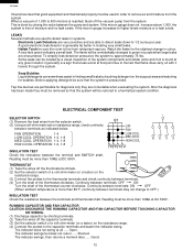
... thermostat clockwise. Continuity between terminals: ON OFF (When ambient temperature is free of a volt-ohm-meter (or a tester) on resistance range, check continuity between the pump and system. LEAKS Several methods are used in order to remove air and moisture from the system. ELECTRICAL COMPONENT TEST SELECTOR SWITCH (1) Remove the lead wires from refrigerant vapours. The flame will be restored to a hermetical sealed condition. Open...
... thermostat clockwise. Continuity between terminals: ON OFF (When ambient temperature is free of a volt-ohm-meter (or a tester) on resistance range, check continuity between the pump and system. LEAKS Several methods are used in order to remove air and moisture from the system. ELECTRICAL COMPONENT TEST SELECTOR SWITCH (1) Remove the lead wires from refrigerant vapours. The flame will be restored to a hermetical sealed condition. Open...
Service Manual
Page 13
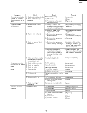
... the relay case. TROUBLESHOOTING GUIDE Symptom Neither fan motor not compressor operate In sufficient cooling No cooling Check Defect 1) Check power supply switch or 1) Fuse open or circuit braker plug and measure the voltage open 2) Plug disconnected 3) Plug connected properly but heat leak excessive 3) Check indoor exchanger inlet/outlet piping temp. FAN CAPACITOR RUNNING CAPACITOR (2) Set selector switch of volt-ohm-meter on the resistance range. (3) Put the probes on the terminals of coil or frost sticks to...
... the relay case. TROUBLESHOOTING GUIDE Symptom Neither fan motor not compressor operate In sufficient cooling No cooling Check Defect 1) Check power supply switch or 1) Fuse open or circuit braker plug and measure the voltage open 2) Plug disconnected 3) Plug connected properly but heat leak excessive 3) Check indoor exchanger inlet/outlet piping temp. FAN CAPACITOR RUNNING CAPACITOR (2) Set selector switch of volt-ohm-meter on the resistance range. (3) Put the probes on the terminals of coil or frost sticks to...
Service Manual
Page 14
... draw compressor operates but stops immediately 1) Compressor winding short 2) Heat source near to terminal defective or improper 1) Fan capacitor defective 2) Power supply voltage is too low 3) Fan motor defective 3) Check 1) Fan motor bearing locked a. Fan motor 4) Wiring to air conditioner 3) Partial restriction in sealed system 1) Check power source voltage, 1) Power source voltage too start voltage drop low 2) Wiring for power supply equipment too small With switch set for cooling, 1) Check power line fuse or fuse or circuit breaker circuit breaker open 2) Check power...
... draw compressor operates but stops immediately 1) Compressor winding short 2) Heat source near to terminal defective or improper 1) Fan capacitor defective 2) Power supply voltage is too low 3) Fan motor defective 3) Check 1) Fan motor bearing locked a. Fan motor 4) Wiring to air conditioner 3) Partial restriction in sealed system 1) Check power source voltage, 1) Power source voltage too start voltage drop low 2) Wiring for power supply equipment too small With switch set for cooling, 1) Check power line fuse or fuse or circuit breaker circuit breaker open 2) Check power...
Service Manual
Page 15
... Change switch Check electric circuit (fan) 2) Overload relay operates as 2) Tighten up 5) Adjust 6) Secure 15 AF-05CML Symptom Fan motor operates but supplies no air when "Selector switch" set at condensor 1) Overload relay operates as the temp. Overload relay operates as outdoor air temp. of outdoor unit is delivered 2) Wiring for outdoor heat exchanger. of outdoor exchanger 4) Rated current is normal but overload relay or internal thermostat cuts out Compressor operates 1) Check switch mechanism in cooling but stops soon Check Defect 1) Check motor rotating direction...
... Change switch Check electric circuit (fan) 2) Overload relay operates as 2) Tighten up 5) Adjust 6) Secure 15 AF-05CML Symptom Fan motor operates but supplies no air when "Selector switch" set at condensor 1) Overload relay operates as the temp. Overload relay operates as outdoor air temp. of outdoor unit is delivered 2) Wiring for outdoor heat exchanger. of outdoor exchanger 4) Rated current is normal but overload relay or internal thermostat cuts out Compressor operates 1) Check switch mechanism in cooling but stops soon Check Defect 1) Check motor rotating direction...
Service Manual
Page 16
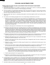
..., etc.). Total the loads estimated for calculating cooling loads in the continental United States having a cooling capacity rating (determined in thickness is considered "Light Construction". The result is based on the ground or over 8 inches in accordance with the largest load. 2. AF-05CML COOLING LOAD ESTIMATE FORM INSTRUCTIONS FOR USING COOLING LOAD ESTIMATE FORM FOR ROOM AIR CONDITIONERS (AHAM PUB. Doors should be considered...
..., etc.). Total the loads estimated for calculating cooling loads in the continental United States having a cooling capacity rating (determined in thickness is considered "Light Construction". The result is based on the ground or over 8 inches in accordance with the largest load. 2. AF-05CML COOLING LOAD ESTIMATE FORM INSTRUCTIONS FOR USING COOLING LOAD ESTIMATE FORM FOR ROOM AIR CONDITIONERS (AHAM PUB. Doors should be considered...
Service Manual
Page 17
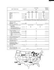
... COOLING LOAD: (BTU per hour to be used for selection of all windows) Single glass Double glass or glass block 3. Roof, uninsulated b. DOORS AND ARCHES CONTINUOUSLY OPENED TO UNCONDITIONED SPACE: (Linear feet of wall.) a. For glass block, multiply the above . AF-05CML HEAT GAIN FROM 1. SUB-TOTAL 10. Outside walls Noth exposure Other than North exposure b. LIGHTS AND ELECTRICAL EQUIPMENT IN USE 8. ROOF...
... COOLING LOAD: (BTU per hour to be used for selection of all windows) Single glass Double glass or glass block 3. Roof, uninsulated b. DOORS AND ARCHES CONTINUOUSLY OPENED TO UNCONDITIONED SPACE: (Linear feet of wall.) a. For glass block, multiply the above . AF-05CML HEAT GAIN FROM 1. SUB-TOTAL 10. Outside walls Noth exposure Other than North exposure b. LIGHTS AND ELECTRICAL EQUIPMENT IN USE 8. ROOF...
Service Manual
Page 18
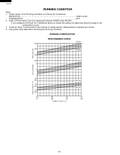
... COOL THERMOSTAT 64˚F 2. is measured between 40%RH and 70%RH. Use power input data when checking the Running Condition. AF-05CML RUNNING CONDITION Note: 1. If you measure the Room Air Conditioner above or below this rating, the data may miss the range of a Room Air Conditioner. RUNNING CONDITION FOR PERFORMANCE CURVE 40%RH 600 Power input (W) 500 70%RH 400 300 40%RH 5 Line current(Amp...
... COOL THERMOSTAT 64˚F 2. is measured between 40%RH and 70%RH. Use power input data when checking the Running Condition. AF-05CML RUNNING CONDITION Note: 1. If you measure the Room Air Conditioner above or below this rating, the data may miss the range of a Room Air Conditioner. RUNNING CONDITION FOR PERFORMANCE CURVE 40%RH 600 Power input (W) 500 70%RH 400 300 40%RH 5 Line current(Amp...
Service Manual
Page 20
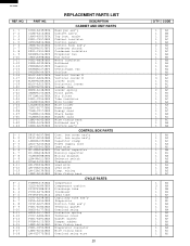
... AF-05CML REPLACEMENT PARTS LIST REF. angle Cabinet insulator Control panel Control knob ass'y Condenser shroud Condenser indulator Propeller fan Fan motor Motor insulator Bulkhead Caseing Centrifugal fan Orifice Vertical louver A Vertical louver B Louver joint Horizontal louver Louver link Louver spring Front panel Air filter Tube insulator Wire holder Wire holder Name badge Energy card Sharp badge Number card Wire fixing band Bulkhead ass'y Orifice ass'y CONTROL BOX PARTS Cont. box angle ass'y Capacitor clamp Power supply cord Lead wire Fan motor capacitor...
... AF-05CML REPLACEMENT PARTS LIST REF. angle Cabinet insulator Control panel Control knob ass'y Condenser shroud Condenser indulator Propeller fan Fan motor Motor insulator Bulkhead Caseing Centrifugal fan Orifice Vertical louver A Vertical louver B Louver joint Horizontal louver Louver link Louver spring Front panel Air filter Tube insulator Wire holder Wire holder Name badge Energy card Sharp badge Number card Wire fixing band Bulkhead ass'y Orifice ass'y CONTROL BOX PARTS Cont. box angle ass'y Capacitor clamp Power supply cord Lead wire Fan motor capacitor...
Service Manual
Page 21
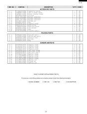
...12 6-13 6-14 PART NO. NO. 3. DESCRIPTION 21 MODEL NUMBER 2. PART NO. 4. REF. ...PARTS Operation manual Left closure frame Right closure frame Closure Window insulator Window insulator Window insulator Screws kit Bag Tapping screw Wood screw Base pan angle Card board Bag Closure ass'y PACKING PARTS...AF-05CML Q'TY CODE 1 AE 1 AH 1 AH 2 AK 1 AH 1 AE 1 AC 1 AW 1 AB 6 AA 7 AA 2 AD 1 AC 1 AC 1 AX 1 AH 1 AN 1 AP 1 AB 1 AB 4 AA 2 AA 7 AA 13 AA 6 AA 5 AA 3 AB 1 AC 4 AA 1 AB 2 AB 1 AB 1 AF 3 AC HOW TO ORDER REPLACEMENT PARTS...
...12 6-13 6-14 PART NO. NO. 3. DESCRIPTION 21 MODEL NUMBER 2. PART NO. 4. REF. ...PARTS Operation manual Left closure frame Right closure frame Closure Window insulator Window insulator Window insulator Screws kit Bag Tapping screw Wood screw Base pan angle Card board Bag Closure ass'y PACKING PARTS...AF-05CML Q'TY CODE 1 AE 1 AH 1 AH 2 AK 1 AH 1 AE 1 AC 1 AW 1 AB 6 AA 7 AA 2 AD 1 AC 1 AC 1 AX 1 AH 1 AN 1 AP 1 AB 1 AB 4 AA 2 AA 7 AA 13 AA 6 AA 5 AA 3 AB 1 AC 4 AA 1 AB 2 AB 1 AB 1 AF 3 AC HOW TO ORDER REPLACEMENT PARTS...


