
Service Manual
Page 1
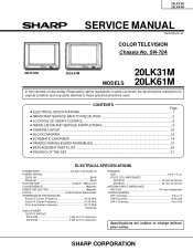
.... SHARP COR1 PORATION CONTENTS Page » ELECTRICAL SPECIFICATIONS ...1 » IMPORTANT SERVICE SAFETY PRECAUTION 2 » LOCATION OF USER'S CONTROL ...4 » INSTALLATION AND SERVICE INSTRUCTIONS 5 » CHASSIS LAYOUT ...10 » BLOCK DIAGRAM ...12 » SCHEMATIC DIAGRAMS ...14 » PRINTED WIRING BOARD ASSEMBLIES 21 » REPLACEMENT PARTS LIST ...24 » PACKING OF THE SET ...31 ELECTRICAL SPECIFICATIONS POWER INPUT 110-220 V AC 50/60 Hz POWER RATING 20LK31M 88 W 20LK61M 98 W PICTURE SIZE 1,194cm2 (185sq inch...
.... SHARP COR1 PORATION CONTENTS Page » ELECTRICAL SPECIFICATIONS ...1 » IMPORTANT SERVICE SAFETY PRECAUTION 2 » LOCATION OF USER'S CONTROL ...4 » INSTALLATION AND SERVICE INSTRUCTIONS 5 » CHASSIS LAYOUT ...10 » BLOCK DIAGRAM ...12 » SCHEMATIC DIAGRAMS ...14 » PRINTED WIRING BOARD ASSEMBLIES 21 » REPLACEMENT PARTS LIST ...24 » PACKING OF THE SET ...31 ELECTRICAL SPECIFICATIONS POWER INPUT 110-220 V AC 50/60 Hz POWER RATING 20LK31M 88 W 20LK61M 98 W PICTURE SIZE 1,194cm2 (185sq inch...
Service Manual
Page 2
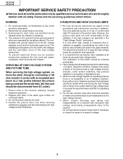
...) between the line cord and power receptacle, when servicing this receiver employs integral implosion protection. 2. 20LK31M 20LK61M IMPORTANT SERVICE SAFETY PRECAUTION Ë Service work should be performed only by connecting a 10k ohm resistor in series with an insulated wire (such as specified in the "High Voltage Check" instructions. Disconnect AC power before servicing. 3. Picture tube in this chassis. Replace with tube of excessive...
...) between the line cord and power receptacle, when servicing this receiver employs integral implosion protection. 2. 20LK31M 20LK61M IMPORTANT SERVICE SAFETY PRECAUTION Ë Service work should be performed only by connecting a 10k ohm resistor in series with an insulated wire (such as specified in the "High Voltage Check" instructions. Disconnect AC power before servicing. 3. Picture tube in this chassis. Replace with tube of excessive...
Service Manual
Page 3
... manner. » Plug the AC cord directly into a 120 volt AC outlet, (Do not use of These characteristics are identified by "å" and shaded areas in the Replacement Parts Lists and 111S222c333h444e555m666777a888ti999c000D111222ia333g444r555a666m777888s999. 000111222333444555666777888999000111222111222333444555666777888999000111222333444555666777888999000111222333444555666777888999000111222111222333444555666777888999000111222333444555666777888999000111222333444555666777888999000111222111222 3 The use an isolation transformer for this service manual, may components rated for...
... manner. » Plug the AC cord directly into a 120 volt AC outlet, (Do not use of These characteristics are identified by "å" and shaded areas in the Replacement Parts Lists and 111S222c333h444e555m666777a888ti999c000D111222ia333g444r555a666m777888s999. 000111222333444555666777888999000111222111222333444555666777888999000111222333444555666777888999000111222333444555666777888999000111222111222333444555666777888999000111222333444555666777888999000111222333444555666777888999000111222111222 3 The use an isolation transformer for this service manual, may components rated for...
Service Manual
Page 4
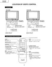
.... 20LK31M 20LK61M LOCATION OF USER'S CONTROL Front Panel 20LK31M LK 20LK61M LK VIDEO/AUDIOIN TERMINALS VIDEO/AUDIOIN TERMINALS POWER Press → On. VOLUME UP/DOWN (+) Increases sound. (-) Decreases sound. Press again → Off. VOLUME UP/DOWN (+) Increases sound. (-) Decreases sound. • In menu mode, changes or selects the TV adjustments. TV Infrared Transmitter Window INPUT Press → Switch to previous channel. MENU Press → Accesses MAIN MENU. Press again → Removes display. • Temporarily displays receiving channel when in Closed Caption mode...
.... 20LK31M 20LK61M LOCATION OF USER'S CONTROL Front Panel 20LK31M LK 20LK61M LK VIDEO/AUDIOIN TERMINALS VIDEO/AUDIOIN TERMINALS POWER Press → On. VOLUME UP/DOWN (+) Increases sound. (-) Decreases sound. Press again → Off. VOLUME UP/DOWN (+) Increases sound. (-) Decreases sound. • In menu mode, changes or selects the TV adjustments. TV Infrared Transmitter Window INPUT Press → Switch to previous channel. MENU Press → Accesses MAIN MENU. Press again → Removes display. • Temporarily displays receiving channel when in Closed Caption mode...
Service Manual
Page 5
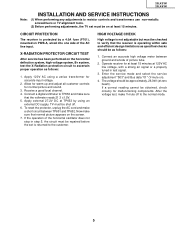
.... 20LK31M 20LK61M Note: INSTALLATION AND SERVICE INSTRUCTIONS (1) When performing any adjustments to resistor controls and transformers use non-metallic screwdrivers or TV alignment tools. (2) Before performing adjustments, the TV set is returned to the customer. Now make sure that the receiver is protected by using a variac transformer for normal picture and sound. 3. X-RADIATION PROTECTOR CIRCUIT TEST After service has been performed on the screen...
.... 20LK31M 20LK61M Note: INSTALLATION AND SERVICE INSTRUCTIONS (1) When performing any adjustments to resistor controls and transformers use non-metallic screwdrivers or TV alignment tools. (2) Before performing adjustments, the TV set is returned to the customer. Now make sure that the receiver is protected by using a variac transformer for normal picture and sound. 3. X-RADIATION PROTECTOR CIRCUIT TEST After service has been performed on the screen...
Service Manual
Page 6
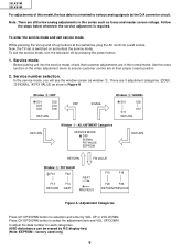
... the video adjustment menu to adjust the data number for selection and enter by R/C display key) (Note: EEPROM - In the service mode, you will see the window screen as window 1. To enter the service mode and exit service mode. While pressing the Vol-up and Ch-up buttons at the sametime, plug the AC cord into the service mode, check that customer adjustments are in Figure A. Service mode. To exit the service mode, turn the television...
... the video adjustment menu to adjust the data number for selection and enter by R/C display key) (Note: EEPROM - In the service mode, you will see the window screen as window 1. To enter the service mode and exit service mode. While pressing the Vol-up and Ch-up buttons at the sametime, plug the AC cord into the service mode, check that customer adjustments are in Figure A. Service mode. To exit the service mode, turn the television...
Service Manual
Page 7
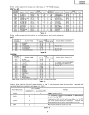
...-up /Ch-down buttons on the TV set at service mode for each categories. B SERVICE POSITION S01 S02 S03 S04 S05 S06 S07 S08 S09 S10 S11 S12 S13 ADJUST ITEM RF AGC VIDEO LEVEL Y-MUTE SUB BIAS R-BIAS G-BIAS B-BIAS R-DRIVE B-DRIVE CONTRAST TINT COLOR BRIGHTNESS DATA RANGE INITIAL...7F 40 00-7F 40 ADJUSTMENT CONTENTS "01":Y-MUTE, "02":V-STOP&Y-MUTE "03":Activate color killer circuit Must be "0F" SIGNAL Table - D 7 Table - FIX VALUE SERVICE POSITION F01 F02 F03 F04 F05 F06 F07 F08 F09 F10 F11 F12 F13 ADJUST ITEM OPTION 1 OPTION 2 E-SAVE TUNER SETUP R-TONE RD R-TONE BD...
...-up /Ch-down buttons on the TV set at service mode for each categories. B SERVICE POSITION S01 S02 S03 S04 S05 S06 S07 S08 S09 S10 S11 S12 S13 ADJUST ITEM RF AGC VIDEO LEVEL Y-MUTE SUB BIAS R-BIAS G-BIAS B-BIAS R-DRIVE B-DRIVE CONTRAST TINT COLOR BRIGHTNESS DATA RANGE INITIAL...7F 40 00-7F 40 ADJUSTMENT CONTENTS "01":Y-MUTE, "02":V-STOP&Y-MUTE "03":Activate color killer circuit Must be "0F" SIGNAL Table - D 7 Table - FIX VALUE SERVICE POSITION F01 F02 F03 F04 F05 F06 F07 F08 F09 F10 F11 F12 F13 ADJUST ITEM OPTION 1 OPTION 2 E-SAVE TUNER SETUP R-TONE RD R-TONE BD...
Service Manual
Page 8
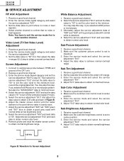
.... 3. Select the service adjustment "S12" and reset data to obtain normal color level. Enter the service mode and select the service adjustment "S11". 4. Make sure the customer color control is obtained. 4. Enter the service mode signal category and select the service adjustment "S01". 3. Video Level (TV Det Video Level) Adjustment 1. Screen Adjustment 1. Enter the service mode Signal category and set to turn off the luminance signal (Y-mute). 5. You may skip this step, if you selected a B/W picture or monoscope. 3. Receive a good local channel...
.... 3. Select the service adjustment "S12" and reset data to obtain normal color level. Enter the service mode and select the service adjustment "S11". 4. Make sure the customer color control is obtained. 4. Enter the service mode signal category and select the service adjustment "S01". 3. Video Level (TV Det Video Level) Adjustment 1. Screen Adjustment 1. Enter the service mode Signal category and set to turn off the luminance signal (Y-mute). 5. You may skip this step, if you selected a B/W picture or monoscope. 3. Receive a good local channel...
Service Manual
Page 9
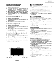
... adjustment. 9 Adjust "D03" bus data to balance the text box position in no-signal state. 2. Enter the service mode DEF category and select the adjustment "D04". 3. Monaural signal: 300Hz, 245mVrms 2. Enter the service mode and select the service adjustment "M02" 5. Receive a good local channel. 2. Vertical-Phase Adjustment 1. Caption Position Adjustment (Horizontal) 1. below) 4. Adjust "D04" data value to get the best linearity. 4. Receive a good local channel. 2. A B Figure C. 20LK31M 20LK61M Ë MTS ADJUSTMENT MTS Level Adjustment 1. Connect...
... adjustment. 9 Adjust "D03" bus data to balance the text box position in no-signal state. 2. Enter the service mode DEF category and select the adjustment "D04". 3. Monaural signal: 300Hz, 245mVrms 2. Enter the service mode and select the service adjustment "M02" 5. Receive a good local channel. 2. Vertical-Phase Adjustment 1. Caption Position Adjustment (Horizontal) 1. below) 4. Adjust "D04" data value to get the best linearity. 4. Receive a good local channel. 2. A B Figure C. 20LK31M 20LK61M Ë MTS ADJUSTMENT MTS Level Adjustment 1. Connect...
Service Manual
Page 14
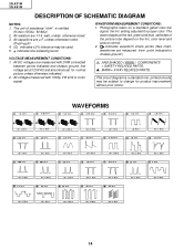
... controls set at the red, green and blue cathodes of resistance "ohm" is a standard one, printed circuits may be subject to chassis ground.) å AND SHADED ( ) COMPONENTS = SAFETY RELATED PARTS. ' MARK= X-RAY RELATED PARTS. Photographs taken on the tint, color level and picture control. 2. indicates line isolated ground. All capacitors are measured with 1000µ V B & W or Color signal. 20LK31M 20LK61M DESCRIPTION OF SCHEMATIC DIAGRAM...
... controls set at the red, green and blue cathodes of resistance "ohm" is a standard one, printed circuits may be subject to chassis ground.) å AND SHADED ( ) COMPONENTS = SAFETY RELATED PARTS. ' MARK= X-RAY RELATED PARTS. Photographs taken on the tint, color level and picture control. 2. indicates line isolated ground. All capacitors are measured with 1000µ V B & W or Color signal. 20LK31M 20LK61M DESCRIPTION OF SCHEMATIC DIAGRAM...
Service Manual
Page 22
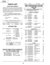
electrical components having such features are identified by å and shaded areas in the Replacement Parts Lists and Schematic Diagrams. The use of a substitute replacement part which have these special safety characteristics identified in this manual; No. Main Unit (20LK61M) - PWB-C DUNTKA222WEV0 - Front AV Unit (20LK61M) - Part No. 5 Description Code PWB-A: DUNTKA221WEV1 (20LK31M) PWB-A: DUNTKA221WEV3 (20LK61M) MAIN UNIT TUNER NOTE : THE PARTS HERE SHOWN ARE SUPPLIED AS AN ASSEMBLY...
electrical components having such features are identified by å and shaded areas in the Replacement Parts Lists and Schematic Diagrams. The use of a substitute replacement part which have these special safety characteristics identified in this manual; No. Main Unit (20LK61M) - PWB-C DUNTKA222WEV0 - Front AV Unit (20LK61M) - Part No. 5 Description Code PWB-A: DUNTKA221WEV1 (20LK31M) PWB-A: DUNTKA221WEV3 (20LK61M) MAIN UNIT TUNER NOTE : THE PARTS HERE SHOWN ARE SUPPLIED AS AN ASSEMBLY...
Service Manual
Page 26
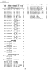
... J Plug, 5-pin (TP2001-5) AB RMC2601 RRMCU0232CEZZ J R/C Receiver AG RDA501 PRDAR0106GJFW X Heat Sink, for IC501 AF RDA602 PRDAR0216PEFW R Heat Sink, for Q602 AE RDA701 PRDAR0238PEFW R Heat Sink, for IC701 AN TP701 QLUGP0102PEZZ R Lug AA LX-BZ3049GEFD J Screw AA LX-BZ3100CEFD J Screw AA LX-TZ3004CEFD J Screw AA PZETM0016CEZZ J Insulator AB QCNW-2047PEZZ R Connecting Cord AK 28 No. AA (20LK61M...
... J Plug, 5-pin (TP2001-5) AB RMC2601 RRMCU0232CEZZ J R/C Receiver AG RDA501 PRDAR0106GJFW X Heat Sink, for IC501 AF RDA602 PRDAR0216PEFW R Heat Sink, for Q602 AE RDA701 PRDAR0238PEFW R Heat Sink, for IC701 AN TP701 QLUGP0102PEZZ R Lug AA LX-BZ3049GEFD J Screw AA LX-BZ3100CEFD J Screw AA LX-TZ3004CEFD J Screw AA PZETM0016CEZZ J Insulator AB QCNW-2047PEZZ R Connecting Cord AK 28 No. AA (20LK61M...
Service Manual
Page 28
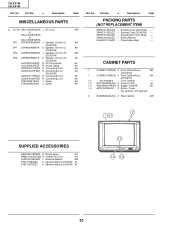
... Foam Wrap - Part No. 5 Description Code PACKING PARTS (NOT REPLACEMENT ITEM) SPAKC0134GJZZ - SPAKC0135GJZZ - SPAKX0002GJZZ - Front Cabinet - 1-2 GCOVA0002GJSA X Cover for R/C AL 1-3 HBDGB0019PESB R Badge, "SHARP" AD 1-4 JBTN-0002GJSC X Button, Power Vol-up/down, CH-up/down 2 GCABB0002GJKA X Rear Cabinet AW 2 1 1-1 LK SUPPLIED ACCESSORIES QANTR0018PEZZ R Rod Antenna AQ RRMCG1339CESB X Infrared R/C Unit AQ RUNTK0165CEZZ J Antenna Adapter AM TiNS-7056GJZZ X Operation Manual (20LK31M) AL TiNS-7057GJZZ X Operation Manual (20LK61M) AL 1-3 1-2 1-4 30...
... Foam Wrap - Part No. 5 Description Code PACKING PARTS (NOT REPLACEMENT ITEM) SPAKC0134GJZZ - SPAKC0135GJZZ - SPAKX0002GJZZ - Front Cabinet - 1-2 GCOVA0002GJSA X Cover for R/C AL 1-3 HBDGB0019PESB R Badge, "SHARP" AD 1-4 JBTN-0002GJSC X Button, Power Vol-up/down, CH-up/down 2 GCABB0002GJKA X Rear Cabinet AW 2 1 1-1 LK SUPPLIED ACCESSORIES QANTR0018PEZZ R Rod Antenna AQ RRMCG1339CESB X Infrared R/C Unit AQ RUNTK0165CEZZ J Antenna Adapter AM TiNS-7056GJZZ X Operation Manual (20LK31M) AL TiNS-7057GJZZ X Operation Manual (20LK61M) AL 1-3 1-2 1-4 30...
Service Manual
Page 29
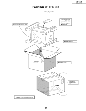
No. No. Part No. 5 Description Code 5 Polyethylene Bag 5 Polyethylene Foam Wrap Operation Manual Infrared R/C Unit Rod Antenna Antenna Adapter 5 Batteries 5 Buffer Material FRONT 5 Packing Case 5 MARK : Not Replacement Items. REAR Use tapes to fix the packing case. 31 Part No. 5 PACKING OF THE SET Description Code Ref. 20LK31M 20LK61M Ref.
No. No. Part No. 5 Description Code 5 Polyethylene Bag 5 Polyethylene Foam Wrap Operation Manual Infrared R/C Unit Rod Antenna Antenna Adapter 5 Batteries 5 Buffer Material FRONT 5 Packing Case 5 MARK : Not Replacement Items. REAR Use tapes to fix the packing case. 31 Part No. 5 PACKING OF THE SET Description Code Ref. 20LK31M 20LK61M Ref.
Service Manual
Page 30
No. No part of the publisher. D SEMEX P SEMEX TQ0967-S Aug. 2000 Printed in any form or by any means, electronic, mechanical, photocopying, recording, or otherwise, without prior written permission of this publication may be reproduced, stored in a retrieval system, or transmitted in Japan MI. Part No. 5 Description Code COPYRIGHT © 2000 BY SHARP CORPORATION ALL RIGHTS RESERVED. 20LK31M 20LK61M Ref. Part No. 5 Description Code Ref. No. KG SHARP CORPORATION AV Systems Group Quality & Reliability Control Center Yaita, Tochigi 329-2193, Japan 32
No. No part of the publisher. D SEMEX P SEMEX TQ0967-S Aug. 2000 Printed in any form or by any means, electronic, mechanical, photocopying, recording, or otherwise, without prior written permission of this publication may be reproduced, stored in a retrieval system, or transmitted in Japan MI. Part No. 5 Description Code COPYRIGHT © 2000 BY SHARP CORPORATION ALL RIGHTS RESERVED. 20LK31M 20LK61M Ref. Part No. 5 Description Code Ref. No. KG SHARP CORPORATION AV Systems Group Quality & Reliability Control Center Yaita, Tochigi 329-2193, Japan 32


