
Instructions for Use
Page 50
... Scanning the channel banks for free channels (receivers only 31 Multi-channel operation 32 Adjusting the sensitivity (transmitters only 32 Adjusting the audio output level (receivers only 33 Adjusting the squelch threshold (receivers only 33 Selecting the standard display 34 Entering a name ...34 Loading the factory-preset default settings 35 Activating/deactivating the pilot tone transmission or pilot tone evaluation .. 35 Activating/deactivating the lock mode 35 Exiting the operating menu 35 If problems occur...
... Scanning the channel banks for free channels (receivers only 31 Multi-channel operation 32 Adjusting the sensitivity (transmitters only 32 Adjusting the audio output level (receivers only 33 Adjusting the squelch threshold (receivers only 33 Selecting the standard display 34 Entering a name ...34 Loading the factory-preset default settings 35 Activating/deactivating the pilot tone transmission or pilot tone evaluation .. 35 Activating/deactivating the lock mode 35 Exiting the operating menu 35 If problems occur...
Instructions for Use
Page 51
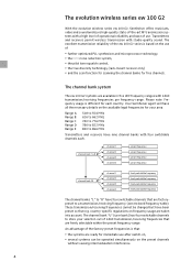
... squelch control, y the true diversity technology (rack-mount receiver only) y and the scan function for scanning the channel banks for each . These transmission/receiving frequencies cannot be operated simultaneously on frequency usage are factorypreset to 866 MHz Transmitters and receivers have four switchable channels that e.g. Transmitters and receivers permit wireless transmission with a high level of operational reliability and ease of use of the factory-preset frequencies is different for free channels. Please note: Frequency...
... squelch control, y the true diversity technology (rack-mount receiver only) y and the scan function for scanning the channel banks for each . These transmission/receiving frequencies cannot be operated simultaneously on frequency usage are factorypreset to 866 MHz Transmitters and receivers have four switchable channels that e.g. Transmitters and receivers permit wireless transmission with a high level of operational reliability and ease of use of the factory-preset frequencies is different for free channels. Please note: Frequency...

Instructions for Use
Page 53
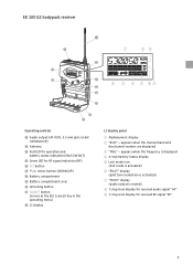
...; Ƹ Operating controls ³ LC display · ̆ button (UP) » ̄ button (DOWN) ¿ SET button ´ POWER button (serves as the ESC (cancel) key in the operating menu) ² Cable grip for power supply DC cable ¶ DC socket for connection of mains unit (DC IN) º Audio output (AF OUT BAL), XLR-3M socket, balanced ¾ Audio output (AF OUT UNBAL), ¼" (6.3 mm) jack socket, unbalanced µ Service interface (DATA) ¸ Antenna input II...
...; Ƹ Operating controls ³ LC display · ̆ button (UP) » ̄ button (DOWN) ¿ SET button ´ POWER button (serves as the ESC (cancel) key in the operating menu) ² Cable grip for power supply DC cable ¶ DC socket for connection of mains unit (DC IN) º Audio output (AF OUT BAL), XLR-3M socket, balanced ¾ Audio output (AF OUT UNBAL), ¼" (6.3 mm) jack socket, unbalanced µ Service interface (DATA) ¸ Antenna input II...
Instructions for Use
Page 54
...; ¶ º ¾ Operating controls ³ Audio output (AF OUT), 3.5 mm jack socket (unbalanced) · Antenna » Red LED for operation and battery status indication (ON/LOW BAT) ¿ Green LED for received RF signal "RF" 7 appears when the channel bank and the channel number are displayed ቤ "MHz" - appears when the frequency is displayed ብ 4-step battery status display ቦ Lock mode icon (lock mode is activated) ቧ "PILOT" display (pilot tone evaluation...
...; ¶ º ¾ Operating controls ³ Audio output (AF OUT), 3.5 mm jack socket (unbalanced) · Antenna » Red LED for operation and battery status indication (ON/LOW BAT) ¿ Green LED for received RF signal "RF" 7 appears when the channel bank and the channel number are displayed ቤ "MHz" - appears when the frequency is displayed ብ 4-step battery status display ቦ Lock mode icon (lock mode is activated) ቧ "PILOT" display (pilot tone evaluation...

Instructions for Use
Page 55
...; Operating controls ³ Microphone/line input (MIC/LINE), 3.5 mm jack socket · Antenna » Red LED for operation and battery status indication (ON/LOW BAT) ¿ Yellow LED for audio signal "AF" 8 appears when the frequency is displayed ብ 4-step battery status display ቦ Lock mode icon (lock mode is activated) ቧ "PILOT" display (pilot tone transmission is activated) ቨ "MUTE" display (audio input is muted) ቩ 7-step level display for audio peak (AF PEAK) ´ SET button...
...; Operating controls ³ Microphone/line input (MIC/LINE), 3.5 mm jack socket · Antenna » Red LED for operation and battery status indication (ON/LOW BAT) ¿ Yellow LED for audio signal "AF" 8 appears when the frequency is displayed ብ 4-step battery status display ቦ Lock mode icon (lock mode is activated) ቧ "PILOT" display (pilot tone transmission is activated) ቨ "MUTE" display (audio input is muted) ቩ 7-step level display for audio peak (AF PEAK) ´ SET button...

Instructions for Use
Page 56
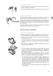
SKP 100 G2 plug-on transmitter ³· » ¿ ´² ቢ ባቤ ብ ¶ º ¾ µ Operating controls ³ Microphone input, XLR-3F socket (unbalanced) · Mechanical locking ring of XLR-3 socket » LC display ¿ SET button ´ ̄ button (DOWN) ² ̆ button (UP) ¶ Red LED for audio signal "AF" 9 appears when the frequency is displayed ብ 4-step battery status display ቦ Lock mode icon (lock mode is activated...
SKP 100 G2 plug-on transmitter ³· » ¿ ´² ቢ ባቤ ብ ¶ º ¾ µ Operating controls ³ Microphone input, XLR-3F socket (unbalanced) · Mechanical locking ring of XLR-3 socket » LC display ¿ SET button ´ ̄ button (DOWN) ² ̆ button (UP) ¶ Red LED for audio signal "AF" 9 appears when the frequency is displayed ብ 4-step battery status display ቦ Lock mode icon (lock mode is activated...

Instructions for Use
Page 57
...: MD 835 microphone head blue: MD 845 microphone head red: ME 865 microphone head » Body of radiomicrophone ¿ Battery compartment (not visible from outside) ´ Display section ² LC display ¶ Turnable protective cap for operating controls (shown removed) The following operating controls become accessible in turn by turning the protective cap: º SET button ¾ ̄ button (DOWN) µ ̆ button (UP) ¸ Red LED for audio signal "AF...
...: MD 835 microphone head blue: MD 845 microphone head red: ME 865 microphone head » Body of radiomicrophone ¿ Battery compartment (not visible from outside) ´ Display section ² LC display ¶ Turnable protective cap for operating controls (shown removed) The following operating controls become accessible in turn by turning the protective cap: º SET button ¾ ̄ button (DOWN) µ ̆ button (UP) ¸ Red LED for audio signal "AF...

Instructions for Use
Page 58
... be replaced (LOW BAT), the transmitter transmits information on its remaining battery/accupack capacity to the EM 100 G2 receiver and the transmitter low battery icon ቧ starts flashing on and the capacity of the batteries/accupack BA 2015 is sufficient. » Red LED flashing: The batteries are/the accupack BA 2015 is going flat (LOW BAT)! ብ EM 100 G2 Indications and displays on the receivers Operation and battery status...
... be replaced (LOW BAT), the transmitter transmits information on its remaining battery/accupack capacity to the EM 100 G2 receiver and the transmitter low battery icon ቧ starts flashing on and the capacity of the batteries/accupack BA 2015 is sufficient. » Red LED flashing: The batteries are/the accupack BA 2015 is going flat (LOW BAT)! ብ EM 100 G2 Indications and displays on the receivers Operation and battery status...
Instructions for Use
Page 64
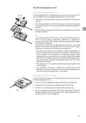
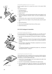
... characteristics of the accupack temperature during charging in the diagram on page 33). 17 The sensor is - y The monitoring of primary cells (batteries) and accupacks. video camera) to the EK 100 G2 bodypack receiver. ̈ Connect one of the supplied line output cables to the recording unit. ̈ Connect the 3.5 mm jack plug to the rack-mount receivers and the switch-off thresholds at the end of inserted primary...
... characteristics of the accupack temperature during charging in the diagram on page 33). 17 The sensor is - y The monitoring of primary cells (batteries) and accupacks. video camera) to the EK 100 G2 bodypack receiver. ̈ Connect one of the supplied line output cables to the recording unit. ̈ Connect the 3.5 mm jack plug to the rack-mount receivers and the switch-off thresholds at the end of inserted primary...
Instructions for Use
Page 65
... flash mount adapter Ƹ will need to be fastened so that the receiver can either use two 1.5 V AA size batteries or the rechargeable Sennheiser BA 2015 accupack. ̈ Press the two unlocking buttons ᕩ and open the battery compartment cover ᕨ. ̈ Insert the two batteries or the BA 2015 accupack as shown in the diagram on page 32). Connecting the microphone/line cable The microphone/line input...
... flash mount adapter Ƹ will need to be fastened so that the receiver can either use two 1.5 V AA size batteries or the rechargeable Sennheiser BA 2015 accupack. ̈ Press the two unlocking buttons ᕩ and open the battery compartment cover ᕨ. ̈ Insert the two batteries or the BA 2015 accupack as shown in the diagram on page 32). Connecting the microphone/line cable The microphone/line input...
Instructions for Use
Page 66
... omni-directional pick-up pattern picks up sound equally from all microphones/usages (see: „Adjusting the sensitivity (transmitters only)" on page 32). Adjust the sensitivity correctly for the following control purposes: y The taking into place with an integrated sensor which is - SKP 100 G2 plug-on transmitter Inserting and replacing the batteries For powering the SKP 100 G2 plug-on the displays, the transmission of transmitter battery status information to...
... omni-directional pick-up pattern picks up sound equally from all microphones/usages (see: „Adjusting the sensitivity (transmitters only)" on page 32). Adjust the sensitivity correctly for the following control purposes: y The taking into place with an integrated sensor which is - SKP 100 G2 plug-on transmitter Inserting and replacing the batteries For powering the SKP 100 G2 plug-on the displays, the transmission of transmitter battery status information to...
Instructions for Use
Page 72
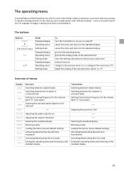
... NAME RESET PILOT LOCK EXIT Receivers Switching between channel banks Switching between the channels in a channel bank Setting a receiving frequency for the channel bank "U" (user bank) Scanning the selected channel bank for free channels ⎯ Adjusting the audio output level Adjusting the squelch threshold Selecting the standard display Entering a name Loading the factory-preset default settings Activating/deactivating the pilot tone evaluation Activating/deactivating the lock mode Exiting the operating menu and returning to the standard display Transmitters Switching between channel...
... NAME RESET PILOT LOCK EXIT Receivers Switching between channel banks Switching between the channels in a channel bank Setting a receiving frequency for the channel bank "U" (user bank) Scanning the selected channel bank for free channels ⎯ Adjusting the audio output level Adjusting the squelch threshold Selecting the standard display Entering a name Loading the factory-preset default settings Activating/deactivating the pilot tone evaluation Activating/deactivating the lock mode Exiting the operating menu and returning to the standard display Transmitters Switching between channel...

Instructions for Use
Page 74
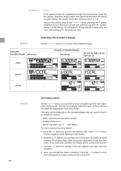
START 04 CH FREE SET STORED AF OUT SET Setting the audio output level LEV +18 Current audio output level SQELCH Setting the squelch threshold STORED SET SQ LO Current squelch threshold STORED DISPLY BANK U ̆ / ̄: 1...8, U (User Bank) SET: Stores the setting 1.04 B . CH 790.100 ̆ / ̄: Channel 01...04 SET: Stores the setting 791.125 ̆ / ̄: Receiving frequency in steps of 6 dB): EM 100 G2:+18...0...-24 dB EK 100 G2: +12...0...-30...
START 04 CH FREE SET STORED AF OUT SET Setting the audio output level LEV +18 Current audio output level SQELCH Setting the squelch threshold STORED SET SQ LO Current squelch threshold STORED DISPLY BANK U ̆ / ̄: 1...8, U (User Bank) SET: Stores the setting 1.04 B . CH 790.100 ̆ / ̄: Channel 01...04 SET: Stores the setting 791.125 ̆ / ̄: Receiving frequency in steps of 6 dB): EM 100 G2:+18...0...-24 dB EK 100 G2: +12...0...-30...

Instructions for Use
Page 78
... "U". Switching between the nine channel banks of the transmitters and receivers. Always set the transmitter and the receiver of a transmission link to the enclosed frequency table. BANK CHAN TUNE SCAN Adjustment tips for free channels In order to ensure intermodulation-free operation of your selection out of 1440 transmission/receiving frequencies that are factory-preset to a transmission/receiving frequency (see: „The channel bank system" on the display. ̈ Use the ̆/̄ buttons...
... "U". Switching between the nine channel banks of the transmitters and receivers. Always set the transmitter and the receiver of a transmission link to the enclosed frequency table. BANK CHAN TUNE SCAN Adjustment tips for free channels In order to ensure intermodulation-free operation of your selection out of 1440 transmission/receiving frequencies that are factory-preset to a transmission/receiving frequency (see: „The channel bank system" on the display. ̈ Use the ̆/̄ buttons...

Instructions for Use
Page 79
... for audio signal (AF) always indicates the audio level - If not enough free channels are used by switched-on transmitters will not be displayed as "free channels". ̈ Select the "SCAN" menu. ̈ Select "START" and confirm your selection by pressing the SET button. EM 100 G2 EM 100 G2 EK 100 G2 Note: For monitoring the adjusted sensitivity, the transmitter's level display for free channels. Before putting the transmission links into operation, we recommend performing an auto scan. ̈ Select a channel...
... for audio signal (AF) always indicates the audio level - If not enough free channels are used by switched-on transmitters will not be displayed as "free channels". ̈ Select the "SCAN" menu. ̈ Select "START" and confirm your selection by pressing the SET button. EM 100 G2 EM 100 G2 EK 100 G2 Note: For monitoring the adjusted sensitivity, the transmitter's level display for free channels. Before putting the transmission links into operation, we recommend performing an auto scan. ̈ Select a channel...
Instructions for Use
Page 81
... segment starts flashing on the display. If you hold down a button, the display starts cycling continuously. ̈ Press the SET button to change to get into the setting mode of the performer for test purposes only. Notes: If the squelch threshold is for whom the adjustments have been made. To enter a name, proceed as : y letters (without pronounciation marks), y numbers from 0 to the previous menu level...
... segment starts flashing on the display. If you hold down a button, the display starts cycling continuously. ̈ Press the SET button to change to get into the setting mode of the performer for test purposes only. Notes: If the squelch threshold is for whom the adjustments have been made. To enter a name, proceed as : y letters (without pronounciation marks), y numbers from 0 to the previous menu level...
Instructions for Use
Page 82
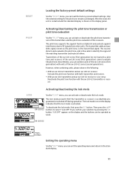
... the buttons can activate or deactivate the pilot tone transmission of the transmitters and the pilot tone evaluation of the ew 100 series (first generation) cannot evaluate the pilot tone. After the reset, the unit is restarted and the standard display is accidentally programmed or switched off during operation. However, when combining units, please observe the following: y With an ew 100 G2 transmitter and an ew 100 G2 receiver...
... the buttons can activate or deactivate the pilot tone transmission of the transmitters and the pilot tone evaluation of the ew 100 series (first generation) cannot evaluate the pilot tone. After the reset, the unit is restarted and the standard display is accidentally programmed or switched off during operation. However, when combining units, please observe the following: y With an ew 100 G2 transmitter and an ew 100 G2 receiver...
Instructions for Use
Page 83
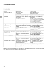
If problems occur Error checklist Problem Possible cause Possible solution No operation indication Batteries are flat or accupack is flat Replace the batteries or recharge the accupack No mains connection (EM 100 G2) Check the connections of the mains unit No RF signal Transmitter and receiver are not on the Set transmitter and receiver to the same channel same channel Transmitter is out of range Check the squelch threshold setting (see: „Adjusting the squelch threshold (receivers only...
If problems occur Error checklist Problem Possible cause Possible solution No operation indication Batteries are flat or accupack is flat Replace the batteries or recharge the accupack No mains connection (EM 100 G2) Check the connections of the mains unit No RF signal Transmitter and receiver are not on the Set transmitter and receiver to the same channel same channel Transmitter is out of range Check the squelch threshold setting (see: „Adjusting the squelch threshold (receivers only...
Instructions for Use
Page 87
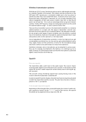
... squelch threshold can be adjusted in a single unit, the plug-on transmitter converts your favourite wired microphone into a radiomicrophone, the bodypack transmitter can be kept low - Field strength-dependent squelch Depending on microphones can accept a wide range of inputs including: omni-directional or cardioid clip-on both the transmitter and the receiver. In the absence of the received RF signal, the receiver's audio output is fixed, please make -up. Please set...
... squelch threshold can be adjusted in a single unit, the plug-on transmitter converts your favourite wired microphone into a radiomicrophone, the bodypack transmitter can be kept low - Field strength-dependent squelch Depending on microphones can accept a wide range of inputs including: omni-directional or cardioid clip-on both the transmitter and the receiver. In the absence of the received RF signal, the receiver's audio output is fixed, please make -up. Please set...

Instructions for Use
Page 93
... product by the responsible Sennheiser service partner) you will help to their characteristics these products have a shorter service life that is principally dependent on our choice, guarantee service comprises, free of charge, the removal of material and manufacturing defects through repair or replacement of either individual parts or the entire device. Depending on the individual frequency of guarantee. provided that...
... product by the responsible Sennheiser service partner) you will help to their characteristics these products have a shorter service life that is principally dependent on our choice, guarantee service comprises, free of charge, the removal of material and manufacturing defects through repair or replacement of either individual parts or the entire device. Depending on the individual frequency of guarantee. provided that...


