
Instructions for Use
Page 3
... 8 System components 8 EK 1038 receiver 9 Special features 9 Operating controls 9 Indications 10 Preparing for use 11 Using the receiver 12 The operating menu of the receiver 13 Configure the receiver 13 Operating menu of the receiver 16 Adjustment tips for the setup menu 18 Locking channels for the user 18 Adjusting the squelch threshold 19 Limiting the volume at the headphone output 20 L 2015 quick charger 22 Special features 22 Operating controls 23 Preparing for use 24 Using the charger 25 Care and...
... 8 System components 8 EK 1038 receiver 9 Special features 9 Operating controls 9 Indications 10 Preparing for use 11 Using the receiver 12 The operating menu of the receiver 13 Configure the receiver 13 Operating menu of the receiver 16 Adjustment tips for the setup menu 18 Locking channels for the user 18 Adjusting the squelch threshold 19 Limiting the volume at the headphone output 20 L 2015 quick charger 22 Special features 22 Operating controls 23 Preparing for use 24 Using the charger 25 Care and...
Instructions for Use
Page 4
... powering on/off (SKP 500 G2 only 46 Selecting the standard display 47 Entering a name 47 Loading the factory-preset default settings 47 Activating/deactivating the pilot tone transmission (PILOT 48 Activating/deactivating the lock mode 48 Exiting the operating menu 48 Troubleshooting 49 Error checklist 49 Recommendations and tips 50 HDX noise reduction 51 Accessories and spare parts 52 EK 1038 receiver 52 L 2015 quick charger 52 Transmitters...
... powering on/off (SKP 500 G2 only 46 Selecting the standard display 47 Entering a name 47 Loading the factory-preset default settings 47 Activating/deactivating the pilot tone transmission (PILOT 48 Activating/deactivating the lock mode 48 Exiting the operating menu 48 Troubleshooting 49 Error checklist 49 Recommendations and tips 50 HDX noise reduction 51 Accessories and spare parts 52 EK 1038 receiver 52 L 2015 quick charger 52 Transmitters...
Instructions for Use
Page 9
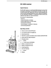
... display y Channel adjustment via rocker button y LED operation indication y LED and display "LowBattery" indication y LED receiving indication Operating controls ³ Volume control and On/Off button · 3.5 mm jack socket for headphones » Receiving antenna ³ ¿ Red LED for operation and battery status indication (LOW BATT/ON) ´ Green LED for a safe transmission. EK 1038 receiver EK 1038 receiver Special features The EK 1038 receiver is characterized by the means of a belt clip. 16 factory-preset UHF frequencies...
... display y Channel adjustment via rocker button y LED operation indication y LED and display "LowBattery" indication y LED receiving indication Operating controls ³ Volume control and On/Off button · 3.5 mm jack socket for headphones » Receiving antenna ³ ¿ Red LED for operation and battery status indication (LOW BATT/ON) ´ Green LED for a safe transmission. EK 1038 receiver EK 1038 receiver Special features The EK 1038 receiver is characterized by the means of a belt clip. 16 factory-preset UHF frequencies...
Instructions for Use
Page 10
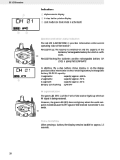
...) does not light up when an RF signal is too weak. Display backlighting After pressing a button, the display remains backlit for approx. 15 seconds. 10 In addition, the 4-step battery status display ᕢ on the display panel provides information on and the capacity of the received transmitter is being received. Red LED flashing:The batteries are/the rechargeable battery BA 2015 is suffi- ¿ cient. EK 1038 receiver ቢ...
...) does not light up when an RF signal is too weak. Display backlighting After pressing a button, the display remains backlit for approx. 15 seconds. 10 In addition, the 4-step battery status display ᕢ on the display panel provides information on and the capacity of the received transmitter is being received. Red LED flashing:The batteries are/the rechargeable battery BA 2015 is suffi- ¿ cient. EK 1038 receiver ቢ...
Instructions for Use
Page 11
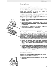
... the L 2015 charger while remaining in order to the receiver's 3.5 mm jack socket (PHONES) ·. 11 EK 1038 receiver Preparing for use . Accupacks ensure economical and environmentally friendly operation of the tourguide UHF system during the night), charge the BA 2015 battery pack of power supply used (batteries or battery pack). It also adapts the battery status display according to self-discharge. The battery pack can alternatively use (e.g. Please observe...
... the L 2015 charger while remaining in order to the receiver's 3.5 mm jack socket (PHONES) ·. 11 EK 1038 receiver Preparing for use . Accupacks ensure economical and environmentally friendly operation of the tourguide UHF system during the night), charge the BA 2015 battery pack of power supply used (batteries or battery pack). It also adapts the battery status display according to self-discharge. The battery pack can alternatively use (e.g. Please observe...

Instructions for Use
Page 12
... links are operated at high volume levels for long periods can clearly and precisely understand the speaker. The red LED ᕤ and the standard display go off ̈ To switch the receiver on, turn the volume control ᕡ counterclockwise until it , the receiver automatically gets off and then on the transmitter. Note: y The receiver has a short switch-on . ̈ Adjust the volume of the charger. The red LED ᕤ lights...
... links are operated at high volume levels for long periods can clearly and precisely understand the speaker. The red LED ᕤ and the standard display go off ̈ To switch the receiver on, turn the volume control ᕡ counterclockwise until it , the receiver automatically gets off and then on the transmitter. Note: y The receiver has a short switch-on . ̈ Adjust the volume of the charger. The red LED ᕤ lights...

Instructions for Use
Page 13
... received on the new channel the green LED ᕥ lights up. º Attaching the receiver to clothing ̈ The receiver is deactivated, no lock mode icon ቤ appears on the display (see "Activating/deactivating the lock mode" on ቤ page 20). ̈ Use the ̆/̄ rocker button (UP/DOWN) º to switch between the channels via the ̆/̄ rocker button (see "Locking channels for daily use the setup menu...
... received on the new channel the green LED ᕥ lights up. º Attaching the receiver to clothing ̈ The receiver is deactivated, no lock mode icon ቤ appears on the display (see "Activating/deactivating the lock mode" on ቤ page 20). ̈ Use the ̆/̄ rocker button (UP/DOWN) º to switch between the channels via the ̆/̄ rocker button (see "Locking channels for daily use the setup menu...

Instructions for Use
Page 14
... the battery compartment. ̈ Press the SET button ᕧ and keep it pressed. ̈ At the same time, turn the volume control ³ clockwise until it clicks to the start display "SETUP" 14 Function of the selected menu: option (̆/̄) Start display without function ESC Operating menu cancel the adjustment and return to the start display "SETUP" Setting mode cancel the entry and return to switch the receiver on the display panel. The "SETUP" display...
... the battery compartment. ̈ Press the SET button ᕧ and keep it pressed. ̈ At the same time, turn the volume control ³ clockwise until it clicks to the start display "SETUP" 14 Function of the selected menu: option (̆/̄) Start display without function ESC Operating menu cancel the adjustment and return to the start display "SETUP" Setting mode cancel the entry and return to switch the receiver on the display panel. The "SETUP" display...

Instructions for Use
Page 15
... the menu LOCK Activating/deactivating the lock mode (see page 20) º TUNE Setting a receiving frequency for the channels (see page 20) and locking channles for the user (see page 20) SQELCH Adjusting the squelch threshold (see page 21) LTD Acitvating/deactivating the limiter at the headphone output (see page 22) Displaying the revision of the firmware* (see see "SWSW-REV REV" on page 22) *software...
... the menu LOCK Activating/deactivating the lock mode (see page 20) º TUNE Setting a receiving frequency for the channels (see page 20) and locking channles for the user (see page 20) SQELCH Adjusting the squelch threshold (see page 21) LTD Acitvating/deactivating the limiter at the headphone output (see page 22) Displaying the revision of the firmware* (see see "SWSW-REV REV" on page 22) *software...

Instructions for Use
Page 16
... so, turn the volume control ᕡ counterclockwise until it clicks If you then restart the receiver you return to the next setting. When canceling the entry with this menu, you will stay in the setting mode of the menu but you get fast and easily to the operating menu of the menu. Operating menu of the receiver The user menu of the current channel (e.g. The new setting flashes on the display until...
... so, turn the volume control ᕡ counterclockwise until it clicks If you then restart the receiver you return to the next setting. When canceling the entry with this menu, you will stay in the setting mode of the menu but you get fast and easily to the operating menu of the menu. Operating menu of the receiver The user menu of the current channel (e.g. The new setting flashes on the display until...

Instructions for Use
Page 18
... and trouble-free reception even if several transmission links are oper- Receiving frequencies are operated simultaneously. The selected channel flashes on the display. ̈ Press the SET button to change. Changing the receiving frequencies of the channels Via the "TUNE" menu you can activate or deactiveate the lock mode. Locking channels for the user Via the "TUNE" menu you can change the receiving frequency of a channel or you have factory-preset receiving frequencies. To deactivate the lock mode you scan lock certain channels (see "Locking channels for the channels...
... and trouble-free reception even if several transmission links are oper- Receiving frequencies are operated simultaneously. The selected channel flashes on the display. ̈ Press the SET button to change. Changing the receiving frequencies of the channels Via the "TUNE" menu you can activate or deactiveate the lock mode. Locking channels for the user Via the "TUNE" menu you can change the receiving frequency of a channel or you have factory-preset receiving frequencies. To deactivate the lock mode you scan lock certain channels (see "Locking channels for the channels...

Instructions for Use
Page 19
... setting that you can quickly switch to lock as described within the chapter "Changing the receiving frequencies of the selected channel flashes on page 20 and confirm your setting. It also suppresses sudden noise when there is no longer sufficient transmitter power received by the guide. The current receiving frequency of the channels" on the display. ̈ Use the ̆/̄ rocker button (UP/DOWN) to store the setting. ̈ The user...
... setting that you can quickly switch to lock as described within the chapter "Changing the receiving frequencies of the selected channel flashes on page 20 and confirm your setting. It also suppresses sudden noise when there is no longer sufficient transmitter power received by the guide. The current receiving frequency of the channels" on the display. ̈ Use the ̆/̄ rocker button (UP/DOWN) to store the setting. ̈ The user...

Instructions for Use
Page 20
...: y If the squelch threshold is adjusted too high, the transmission range will be reduced about approx. 15 dB. This setting is not available on , the maximum possible volume of the firmware installed in the setting mode of other receivers (slaves), allowing you can switch the limiter on and off . Therefore, always adjust the squelch threshold to an arbitrary number of the "SQELCH" menu, pressing the...
...: y If the squelch threshold is adjusted too high, the transmission range will be reduced about approx. 15 dB. This setting is not available on , the maximum possible volume of the firmware installed in the setting mode of other receivers (slaves), allowing you can switch the limiter on and off . Therefore, always adjust the squelch threshold to an arbitrary number of the "SQELCH" menu, pressing the...

Instructions for Use
Page 28
...; Sound inlet basket · Color-coded identification ring for microphone heads y green: MD 835 microphone head y blue: MD 845 microphone head y red: ME 865 microphone head » Body of radiomicrophone ¿ Battery compartment (not visible from outside) ´ Display section ² LC display ¶ Turnable protective cap for operating controls (shown removed) The following operating controls become accessible in turn by turning the protective cap: º SET button ¾...
...; Sound inlet basket · Color-coded identification ring for microphone heads y green: MD 835 microphone head y blue: MD 845 microphone head y red: ME 865 microphone head » Body of radiomicrophone ¿ Battery compartment (not visible from outside) ´ Display section ² LC display ¶ Turnable protective cap for operating controls (shown removed) The following operating controls become accessible in turn by turning the protective cap: º SET button ¾...

Instructions for Use
Page 31
... the sound inlet basket (turn counterclockwise) and remove it tight. 31 Operation and battery status indication The red LED (LOW BAT/ON) ¸ provides information on the current operating state of the radiomicrophone: Red LED lit up: The radiomicrophone is switched on the radiomicrophone and screw it . ̈ Remove the foam insert. ̈ Use a slightly damp cloth to time. Red LED flashing:The batteries...
... the sound inlet basket (turn counterclockwise) and remove it tight. 31 Operation and battery status indication The red LED (LOW BAT/ON) ¸ provides information on the current operating state of the radiomicrophone: Red LED lit up: The radiomicrophone is switched on the radiomicrophone and screw it . ̈ Remove the foam insert. ̈ Use a slightly damp cloth to time. Red LED flashing:The batteries...

Instructions for Use
Page 32
... audio peak (AF PEAK) ´ Charging contacts » ² SET button ¶ ̄/̆ rocker button (UP/DOWN) º Battery compartment ¿ ´ ¾ Battery compartment cover ² µ Unlocking button ¶ ¸ ON/OFF button (serves as ESC (cancel) key in the operating menu) º ¹ LC display ¾ Ƹ MUTE switch µ Preparing for use Inserting and changing the battery For powering the transmitter, two 1.5 V AA size batteries...
... audio peak (AF PEAK) ´ Charging contacts » ² SET button ¶ ̄/̆ rocker button (UP/DOWN) º Battery compartment ¿ ´ ¾ Battery compartment cover ² µ Unlocking button ¶ ¸ ON/OFF button (serves as ESC (cancel) key in the operating menu) º ¹ LC display ¾ Ƹ MUTE switch µ Preparing for use Inserting and changing the battery For powering the transmitter, two 1.5 V AA size batteries...

Instructions for Use
Page 35
... stored settings. Operation and battery status indication The red LED (LOW BAT/ON) ᕣ provides information on the display. The red LED » goes off when the standard display is shown on and the capacity of the transmitter: » Red LED lit up . ̈ To switch the transmitter off . Ƹ ̈ Set the MUTE switch ¹ to retransmit the audio signal. The red ¸ » LED » lights...
... stored settings. Operation and battery status indication The red LED (LOW BAT/ON) ᕣ provides information on the display. The red LED » goes off when the standard display is shown on and the capacity of the transmitter: » Red LED lit up . ̈ To switch the transmitter off . Ƹ ̈ Set the MUTE switch ¹ to retransmit the audio signal. The red ¸ » LED » lights...

Instructions for Use
Page 43
... PHANTO SET PTM. The operating menu of the transmitters evolution wireless series G 2 Overview of the operating menu of the transmitters SET EXIT BANK Changing the channel bank SET BANK 1 Current channel bank STORED CHAN Changing the channel SET 1.03 B.CH Current channel (display depends on "DISPLY" setting) STORED TUNE Setting the frequency for channel bank "U" SET 790.025 MHz Current frequency on /off activated or deactivated STORED SET DISPLY FREQ Switching between the Current standard display standard displays...
... PHANTO SET PTM. The operating menu of the transmitters evolution wireless series G 2 Overview of the operating menu of the transmitters SET EXIT BANK Changing the channel bank SET BANK 1 Current channel bank STORED CHAN Changing the channel SET 1.03 B.CH Current channel (display depends on "DISPLY" setting) STORED TUNE Setting the frequency for channel bank "U" SET 790.025 MHz Current frequency on /off activated or deactivated STORED SET DISPLY FREQ Switching between the Current standard display standard displays...

Instructions for Use
Page 45
... operating menu Adjustment tips for the operating menu Switching between channel banks Via the "BANK" menu, you can switch between the transmitter's nine channel banks. When switching from one of the channel banks "1" to "8" and then select the "TUNE" menu, the transmitter automatically switches to be stored in a channel bank. Note: When using the transmitter with the lowest channel number is automatically displayed. Switching between the channels in 25-kHz steps within the preset frequency range...
... operating menu Adjustment tips for the operating menu Switching between channel banks Via the "BANK" menu, you can switch between the transmitter's nine channel banks. When switching from one of the channel banks "1" to "8" and then select the "TUNE" menu, the transmitter automatically switches to be stored in a channel bank. Note: When using the transmitter with the lowest channel number is automatically displayed. Switching between the channels in 25-kHz steps within the preset frequency range...

Instructions for Use
Page 57
... Sale of Goods do not affect the product's value or fitness for any country throughout the world in the instructions for use. The warranty period begins on the frequency of use) y faults resulting from a product during the course of a warranty claim shall become void if the product is defined as use (e.g. operating errors, mechanical damage, incorrect operating voltage) Proper use...
... Sale of Goods do not affect the product's value or fitness for any country throughout the world in the instructions for use. The warranty period begins on the frequency of use) y faults resulting from a product during the course of a warranty claim shall become void if the product is defined as use (e.g. operating errors, mechanical damage, incorrect operating voltage) Proper use...

