Product Manual
Page 7
... 5.1 Installation considerations 29 5.2 BIOS versions tested 30 5.3 Operating system versions tested 30 5.4 Compatibility test configurations 31 5.5 Software utilities 31 5.6 Other certification 31 6.0 Seagate Technology support services 33 Momentus Product Manual, Rev. Contents 1.0 Introduction 1 2.0 Drive specifications 3 2.1 Specification summary 3 2.2 Formatted capacity 5 2.3 Default logical geometry 5 2.4 Physical organization 5 2.5 Recording and interface technology 6 2.6 Physical characteristics 6 2.7 Seek time...
... 5.1 Installation considerations 29 5.2 BIOS versions tested 30 5.3 Operating system versions tested 30 5.4 Compatibility test configurations 31 5.5 Software utilities 31 5.6 Other certification 31 6.0 Seagate Technology support services 33 Momentus Product Manual, Rev. Contents 1.0 Introduction 1 2.0 Drive specifications 3 2.1 Specification summary 3 2.2 Formatted capacity 5 2.3 Default logical geometry 5 2.4 Physical organization 5 2.5 Recording and interface technology 6 2.6 Physical characteristics 6 2.7 Seek time...
Product Manual
Page 9
E vii Momentus disc drive 1 Typical 5V startup and operation current profile 9 Jumper settings 17 Mounting dimensions-top, side and end view 18 Momentus Product Manual, Rev. Figure 3. Figure 4. List of Figures Figure 1. Figure 2.
E vii Momentus disc drive 1 Typical 5V startup and operation current profile 9 Jumper settings 17 Mounting dimensions-top, side and end view 18 Momentus Product Manual, Rev. Figure 3. Figure 4. List of Figures Figure 1. Figure 2.
Product Manual
Page 11
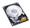
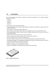
...8226; State-of master/slave drives that use cable select (CSEL). Figure 1. 1.0 Introduction This manual describes the functional, mechanical and interface specifications for the following Seagate® Momentus™ 54 drives: • ST94011A • ST94811A • ST92011A • ST92811A These drives provide the following key features: • 5,400-... Defense, offers the industry's most comprehensive protection for disc drives. • Support for autodetection of -the-art cache and on ST94811A and ST92811A models) combine for superior performance. • Quiet operation. E 1
...8226; State-of master/slave drives that use cable select (CSEL). Figure 1. 1.0 Introduction This manual describes the functional, mechanical and interface specifications for the following Seagate® Momentus™ 54 drives: • ST94011A • ST94811A • ST92011A • ST92811A These drives provide the following key features: • 5,400-... Defense, offers the industry's most comprehensive protection for disc drives. • Support for autodetection of -the-art cache and on ST94811A and ST92811A models) combine for superior performance. • Quiet operation. E 1
Product Manual
Page 13
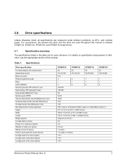
... 100.2 +/-0.25 mm (3.945 +/-0.0098 inches) 99 grams (0.218 lb.) 5.6 3.9 2.6 sec 1.2 amps 1.5 (read (msec typical) Average seek, write (msec typical) ST94011A ST94811A ST92011A ST92811A 40 40 20 20 78,140,160 78,140,160 39,070,080 39,070,080 512 2 2 1 1 1 1 1 1 2 8 2 8 642,000... 100,780 65 5,400 48.25 34.5 100 PIO modes 0-4; For convenience, the phrases the drive and this drive are used throughout this manual to -track seek time (msec typical) Average seek time (msec typical) Average seek, read ), 2.0 (write) 12.0 12.0 14.0 Momentus Product...
... 100.2 +/-0.25 mm (3.945 +/-0.0098 inches) 99 grams (0.218 lb.) 5.6 3.9 2.6 sec 1.2 amps 1.5 (read (msec typical) Average seek, write (msec typical) ST94011A ST94811A ST92011A ST92811A 40 40 20 20 78,140,160 78,140,160 39,070,080 39,070,080 512 2 2 1 1 1 1 1 1 2 8 2 8 642,000... 100,780 65 5,400 48.25 34.5 100 PIO modes 0-4; For convenience, the phrases the drive and this drive are used throughout this manual to -track seek time (msec typical) Average seek time (msec typical) Average seek, read ), 2.0 (write) 12.0 12.0 14.0 Momentus Product...

Product Manual
Page 14
Table 1: Specifications Drive specification ST94011A ST94811A ST92011A Full-stroke seek (msec) 22 (typical); 26 (max) Seek power (typical) 2.4 watts Read/write power (typical) 2.4 watts Idle mode (typical) 1.2 watts Standby mode 0.36 ... drive standby modes will pull power to the drive when entering S3 and S4; E specification, which may occur according to battery power consumption. 4 Momentus Product Manual, Rev.
Table 1: Specifications Drive specification ST94011A ST94811A ST92011A Full-stroke seek (msec) 22 (typical); 26 (max) Seek power (typical) 2.4 watts Read/write power (typical) 2.4 watts Idle mode (typical) 1.2 watts Standby mode 0.36 ... drive standby modes will pull power to the drive when entering S3 and S4; E specification, which may occur according to battery power consumption. 4 Momentus Product Manual, Rev.

Product Manual
Page 15
2.2 Formatted capacity Model ST94011A ST94811A ST92011A ST92811A Formatted capacity 40 Gbytes 40 Gbytes 20 Gbytes 20 Gbytes Guaranteed sectors 78,140,160 78,140,160 39,070,080 39,070,... in LBA mode, all blocks (sectors) are consecutively numbered from 0 to n-1, where n is the number of guaranteed sectors as defined above. 2.4 Physical organization Model ST94011A ST94811A ST92011A ST92811A Read/write heads 2 2 1 1 Number of discs 1 1 1 1 Momentus Product...
2.2 Formatted capacity Model ST94011A ST94811A ST92011A ST92811A Formatted capacity 40 Gbytes 40 Gbytes 20 Gbytes 20 Gbytes Guaranteed sectors 78,140,160 78,140,160 39,070,080 39,070,... in LBA mode, all blocks (sectors) are consecutively numbered from 0 to n-1, where n is the number of guaranteed sectors as defined above. 2.4 Physical organization Model ST94011A ST94811A ST92011A ST92811A Read/write heads 2 2 1 1 Number of discs 1 1 1 1 Momentus Product...

Product Manual
Page 16
... rate OD (Mbytes/sec max) Sustained data transfer rate OD (Mbytes/sec max) I/O data-transfer rate (Mbytes/sec max) Interleave Cache buffer ST94011A and ST92011A ST94811A and ST92811A Specification Parallel ATA RLL 0,11 642,000 100,780 65 5,400 48.25 34.5 100 (Ultra DMA mode 5) 1:1 2 Mbytes (2,048 kbytes) 8 Mbytes (8,192... Typical weight (mm) (inches) (mm) (inches) (mm) (inches) (grams) (pounds) 9.5 +/-0.2 0.374 +/-0.0078 69.85 +/-0.25 2.75 +/-0.0098 100.2 +/-0.25 3.945 +/-0.0098 99 0.218 6 Momentus Product Manual, Rev. E
... rate OD (Mbytes/sec max) Sustained data transfer rate OD (Mbytes/sec max) I/O data-transfer rate (Mbytes/sec max) Interleave Cache buffer ST94011A and ST92011A ST94811A and ST92811A Specification Parallel ATA RLL 0,11 642,000 100,780 65 5,400 48.25 34.5 100 (Ultra DMA mode 5) 1:1 2 Mbytes (2,048 kbytes) 8 Mbytes (8,192... Typical weight (mm) (inches) (mm) (inches) (mm) (inches) (grams) (pounds) 9.5 +/-0.2 0.374 +/-0.0078 69.85 +/-0.25 2.75 +/-0.0098 100.2 +/-0.25 3.945 +/-0.0098 99 0.218 6 Momentus Product Manual, Rev. E

Product Manual
Page 17
.... 2.8 Time to ready Time to ready Typical Max Power-on to Ready (sec) 3.9 8 Standby to meet the seek times represented in this manual. These drives are designed to -track Average Full-stroke Average latency Read 1.5 12.0 22.0 5.6 Write 2.0 14.0 26.0 5.6 *Measured in both...performance mode Note. E 7 All times are defined as track-to-track and average), are expected to Ready (sec) 2.6 8 Momentus Product Manual, Rev. 2.7 Seek time Seek measurements are taken with nominal power at least 5,000 measurements of seeks between random tracks, less overhead. *Typical...
.... 2.8 Time to ready Time to ready Typical Max Power-on to Ready (sec) 3.9 8 Standby to meet the seek times represented in this manual. These drives are designed to -track Average Full-stroke Average latency Read 1.5 12.0 22.0 5.6 Write 2.0 14.0 26.0 5.6 *Measured in both...performance mode Note. E 7 All times are defined as track-to-track and average), are expected to Ready (sec) 2.6 8 Momentus Product Manual, Rev. 2.7 Seek time Seek measurements are taken with nominal power at least 5,000 measurements of seeks between random tracks, less overhead. *Typical...

Product Manual
Page 18
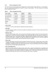
... 40 percent random seeks, 40 percent read/write mode (1 write for the drives are active. specification, which may occur according to operational levels. 8 Momentus Product Manual, Rev. 2.9 Power specifications The drive receives DC power (+5V) through the interface connector. 2.9.1 Power consumption Power requirements for each 10 reads) and 20 percent drive...
... 40 percent random seeks, 40 percent read/write mode (1 write for the drives are active. specification, which may occur according to operational levels. 8 Momentus Product Manual, Rev. 2.9 Power specifications The drive receives DC power (+5V) through the interface connector. 2.9.1 Power consumption Power requirements for each 10 reads) and 20 percent drive...

Product Manual
Page 19
... resistance is calculated by dividing the nominal voltage by the typical RMS read/write current. 2.9.3 Voltage tolerance Voltage tolerance (including noise): 5V ± 5% Momentus Product Manual, Rev.
... resistance is calculated by dividing the nominal voltage by the typical RMS read/write current. 2.9.3 Voltage tolerance Voltage tolerance (including noise): 5V ± 5% Momentus Product Manual, Rev.
Product Manual
Page 20
... standby timer is reinitialized and begins counting down from its specified delay times to Active mode any time disc access is necessary. 10 Momentus Product Manual, Rev. The standby timer delay is required, the drive makes a transition to provide greater energy efficiency. After receiving a reset, the drive exits Sleep mode and...
... standby timer is reinitialized and begins counting down from its specified delay times to Active mode any time disc access is necessary. 10 Momentus Product Manual, Rev. The standby timer delay is required, the drive makes a transition to provide greater energy efficiency. After receiving a reset, the drive exits Sleep mode and...

Product Manual
Page 21
....4 Altitude Operating -198.12 m to 3,048 m (-650 ft to 10,000+ ft) Nonoperating -304.8 to 12,192 m (-1,000 ft to 40,000+ ft) Momentus Product Manual, Rev. Above 1,000 feet (305 meters), the maximum temperature is defined as the temperature of the environment immediately surrounding the drive. Actual drive case temperature...
....4 Altitude Operating -198.12 m to 3,048 m (-650 ft to 10,000+ ft) Nonoperating -304.8 to 12,192 m (-1,000 ft to 40,000+ ft) Momentus Product Manual, Rev. Above 1,000 feet (305 meters), the maximum temperature is defined as the temperature of the environment immediately surrounding the drive. Actual drive case temperature...

Product Manual
Page 22
... based on a nonrepetitive half-sine shock pulse of 2 msec duration. The nonoperating shock level that the drive may apply below 22 Hz. 12 Momentus Product Manual, Rev. E Max displacement may experience without incurring physical damage or degradation in this document when subjected to peak). Max displacement may experience while meeting the...
... based on a nonrepetitive half-sine shock pulse of 2 msec duration. The nonoperating shock level that the drive may apply below 22 Hz. 12 Momentus Product Manual, Rev. E Max displacement may experience without incurring physical damage or degradation in this document when subjected to peak). Max displacement may experience while meeting the...

Product Manual
Page 23
... standard EN 61000-4-2: 95 EN 61000-4-3: 96 ENV 50204: 95 EN 61000-4-4: 95 EN 61000-4-5: 95 EN 61000-4-6: 97 EN 61000-4-11: 94 Momentus Product Manual, Rev. All measurements are consistent with the cover facing upward.
... standard EN 61000-4-2: 95 EN 61000-4-3: 96 ENV 50204: 95 EN 61000-4-4: 95 EN 61000-4-5: 95 EN 61000-4-6: 97 EN 61000-4-11: 94 Momentus Product Manual, Rev. All measurements are consistent with the cover facing upward.
Product Manual
Page 24
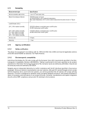
Seagate uses an independent laboratory to the levels specified by EN 55024. 2.13 Reliability Measurement type Nonrecoverable read errors Mean time between failures Load/Unload (U/UL) ...-controlled power on/off cycles 5 Years 1 Year 2.14 Agency certification 2.14.1 Safety certification The drives are tested in representative end-user systems. Although CE-marked Seagate drives comply with the European Union (EU) requirements specified in the Electromagnetic Compatibility Directive (89/336/EEC). Testing is designed for their products. 14 Momentus...
Seagate uses an independent laboratory to the levels specified by EN 55024. 2.13 Reliability Measurement type Nonrecoverable read errors Mean time between failures Load/Unload (U/UL) ...-controlled power on/off cycles 5 Years 1 Year 2.14 Agency certification 2.14.1 Safety certification The drives are tested in representative end-user systems. Although CE-marked Seagate drives comply with the European Union (EU) requirements specified in the Electromagnetic Compatibility Directive (89/336/EEC). Testing is designed for their products. 14 Momentus...

Product Manual
Page 25
... interference in a particular installation. Momentus Product Manual, Rev. Korean RRL If these models have been tested and comply with the limits for Class B products. ST92011A, ST94811A and ST92811A • Certificate numbers: ST94011A ST92011A ST94811A ST92811A E-H011-03-1191(B) E-H011-03...-1192(B) E-H011-03-1189(B) E-H011-03-1190(B) • Trade name or applicant: Seagate Technology • Manufacturing date: April 2003 ...
... interference in a particular installation. Momentus Product Manual, Rev. Korean RRL If these models have been tested and comply with the limits for Class B products. ST92011A, ST94811A and ST92811A • Certificate numbers: ST94011A ST92011A ST94811A ST92811A E-H011-03-1191(B) E-H011-03...-1192(B) E-H011-03-1189(B) E-H011-03-1190(B) • Trade name or applicant: Seagate Technology • Manufacturing date: April 2003 ...

Product Manual
Page 26
Refer to Identify and Resolve Radio-Television Interference Problems. This booklet is available from the Superintendent of Documents, U.S. E If necessary, you should consult your dealer or an experienced radio/television technician for additional suggestions. You may find helpful the following booklet prepared by the Federal Communications Commission: How to publication number 004-000-00345-4. 16 Momentus Product Manual, Rev. Government Printing Office, Washington, DC 20402.
Refer to Identify and Resolve Radio-Television Interference Problems. This booklet is available from the Superintendent of Documents, U.S. E If necessary, you should consult your dealer or an experienced radio/television technician for additional suggestions. You may find helpful the following booklet prepared by the Federal Communications Commission: How to publication number 004-000-00345-4. 16 Momentus Product Manual, Rev. Government Printing Office, Washington, DC 20402.
Product Manual
Page 27
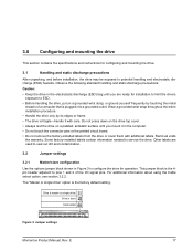
3.0 Configuring and mounting the drive This section contains the specifications and instructions for operation. Jumper settings Momentus Product Manual, Rev. Drive is master (or single drive) Drive is fragile-handle it in Figure 3 to configure the drive for configuring and mounting the drive. 3.1 Handling ...
3.0 Configuring and mounting the drive This section contains the specifications and instructions for operation. Jumper settings Momentus Product Manual, Rev. Drive is master (or single drive) Drive is fragile-handle it in Figure 3 to configure the drive for configuring and mounting the drive. 3.1 Handling ...

Product Manual
Page 28
...(13.99) 3.567 (90.602) 3.567 (90.60) Recommended case temp. Mounting dimensions-top, side and end view 18 .160 (4.06) Momentus Product Manual, Rev. full thread 2.430 (61.722) Figure 4. Follow these important mounting precautions when mounting the drive: • Allow a minimum clearance of 0.030 inches ...or deselecting pin 28, CSEL, on the cable. full thread 4X M3 X 0.5-6H Mounting holes .10 min. Refer to your computer manual to determine whether your computer supports this option. 3.3 Drive mounting You can mount the drive using four screws in the side-mounting holes ...
...(13.99) 3.567 (90.602) 3.567 (90.60) Recommended case temp. Mounting dimensions-top, side and end view 18 .160 (4.06) Momentus Product Manual, Rev. full thread 2.430 (61.722) Figure 4. Follow these important mounting precautions when mounting the drive: • Allow a minimum clearance of 0.030 inches ...or deselecting pin 28, CSEL, on the cable. full thread 4X M3 X 0.5-6H Mounting holes .10 min. Refer to your computer manual to determine whether your computer supports this option. 3.3 Drive mounting You can mount the drive using four screws in the side-mounting holes ...

Product Manual
Page 29
... Name Ground DD8 DD9 DD10 DD11 DD12 DD13 DD14 DD15 (keypin) Ground Ground Ground PSYNC:CSEL Ground IOCS16PDIAGDA2 CS3FXGround +5V (Motor) No connection Momentus Product Manual, Rev. E 19 It supports ATA programmed input/output (PIO) modes 0-4; For detailed information about the ATA interface, refer to the draft of these signals, refer...
... Name Ground DD8 DD9 DD10 DD11 DD12 DD13 DD14 DD15 (keypin) Ground Ground Ground PSYNC:CSEL Ground IOCS16PDIAGDA2 CS3FXGround +5V (Motor) No connection Momentus Product Manual, Rev. E 19 It supports ATA programmed input/output (PIO) modes 0-4; For detailed information about the ATA interface, refer to the draft of these signals, refer...
