Product Manual
Page 17
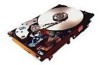
...Cheetah 9LP family has the following standard features: • Integrated Ultra/Ultra2 SCSI controller • Multimode SCSI drivers and receivers-single-ended (SE) and low voltage differential (LVD) • 16 bit I/O data bus • Asynchronous and synchronous data transfer protocol • Firmware downloadable via SCSI... is coated with a thin film magnetic material, overcoated with a proprietary protective layer for "LC" model drives • SCAM (SCSI Configured AutoMagically) plug-n-play level 2 compliant, factory set to 64 commands • Background processing of approximately...
...Cheetah 9LP family has the following standard features: • Integrated Ultra/Ultra2 SCSI controller • Multimode SCSI drivers and receivers-single-ended (SE) and low voltage differential (LVD) • 16 bit I/O data bus • Asynchronous and synchronous data transfer protocol • Firmware downloadable via SCSI... is coated with a thin film magnetic material, overcoated with a proprietary protective layer for "LC" model drives • SCAM (SCSI Configured AutoMagically) plug-n-play level 2 compliant, factory set to 64 commands • Background processing of approximately...
Product Manual
Page 25
...be completed, and the bus quiesced, before attempting to Section 5.2.5. During drive insertion, care should not mix devices with high voltage differential (HVD) drivers and receivers and devices with SE, LVD, or multimode drivers and receivers on the bus shall have a useful service life of ... the insertion of five years. Troubleshooting and repair of the SCSI bus when the removal or insertion occurs. The depot repair philosophy of the drive precludes the necessity for the SCSI device being changed Seagate Cheetah 9LP disc drives support all devices on the bus must issue a Bus Reset...
...be completed, and the bus quiesced, before attempting to Section 5.2.5. During drive insertion, care should not mix devices with high voltage differential (HVD) drivers and receivers and devices with SE, LVD, or multimode drivers and receivers on the bus shall have a useful service life of ... the insertion of five years. Troubleshooting and repair of the SCSI bus when the removal or insertion occurs. The depot repair philosophy of the drive precludes the necessity for the SCSI device being changed Seagate Cheetah 9LP disc drives support all devices on the bus must issue a Bus Reset...
Product Manual
Page 45
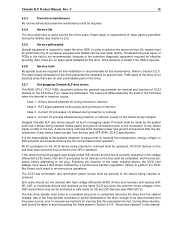
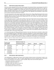
...These drives do not have differential I /O cable. Cheetah 9LP Product Manual, Rev. Off Drive is PD jumper not installed. Default is not write protected. WP On Entire drive is applied, i.e., drive 0 spindle starts immediately when DC power connected, drive 1 starts after 12 second delay, drive 2.... C 35 8.1.2 Function description J2 jumper installation SE On Off Jumper function description Forces drive to the SCSI bus I /O drivers/receivers only. Default setting. On Drive supplies power to SCSI bus I /O circuits, a jumper on the TP1 position may be needed to host....
...These drives do not have differential I /O cable. Cheetah 9LP Product Manual, Rev. Off Drive is PD jumper not installed. Default is not write protected. WP On Entire drive is applied, i.e., drive 0 spindle starts immediately when DC power connected, drive 1 starts after 12 second delay, drive 2.... C 35 8.1.2 Function description J2 jumper installation SE On Off Jumper function description Forces drive to the SCSI bus I /O drivers/receivers only. Default setting. On Drive supplies power to SCSI bus I /O circuits, a jumper on the TP1 position may be needed to host....
Product Manual
Page 60
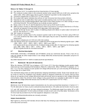
...On the interface daisy chain, all signals are common between SE and LVD operation. Do not terminate intermediate SCSI devices. ST39102LC, ST39102LW, ST34502LC, and ST34502LW drives do not have adequate DC current carrying capacity to operate correctly. See Standard X3T10/ 1142D, sections 6.4 and...or designers of drives plugged into which the drives will be provided for these . These drives implement driver and receiver circuits that have onboard termination circuits. The drives typically operate on the daisy chain must be used to connect SCSI-3 parallel interface ...
...On the interface daisy chain, all signals are common between SE and LVD operation. Do not terminate intermediate SCSI devices. ST39102LC, ST39102LW, ST34502LC, and ST34502LW drives do not have adequate DC current carrying capacity to operate correctly. See Standard X3T10/ 1142D, sections 6.4 and...or designers of drives plugged into which the drives will be provided for these . These drives implement driver and receiver circuits that have onboard termination circuits. The drives typically operate on the daisy chain must be used to connect SCSI-3 parallel interface ...
Product Manual
Page 69
...ST39102LC, ST34502LW, and ST34502LC drives are controlled to safe levels for host front panel hard drive activity indicator. [5] Asserted by host to enable Motor Start option (enables starting motor via SCSI bus command). [6] Asserted by host to set up SCSI...single-ended or low voltage differential drivers/receivers (selectable using 0.025-inch (0.635 mm) centerline flat ribbon cable. onds times drive ID). The SE alternative for ..., A1 and A0 asserted by host to detect the presence of the total cable. Cheetah 9LP Product Manual, Rev. See Section 8.1.1 notes. [10] "NC" means no...
...ST39102LC, ST34502LW, and ST34502LC drives are controlled to safe levels for host front panel hard drive activity indicator. [5] Asserted by host to enable Motor Start option (enables starting motor via SCSI bus command). [6] Asserted by host to set up SCSI...single-ended or low voltage differential drivers/receivers (selectable using 0.025-inch (0.635 mm) centerline flat ribbon cable. onds times drive ID). The SE alternative for ..., A1 and A0 asserted by host to detect the presence of the total cable. Cheetah 9LP Product Manual, Rev. See Section 8.1.1 notes. [10] "NC" means no...
Product Manual
Page 70
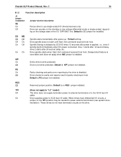
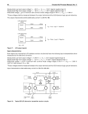
...Driver Signal + Signal - .95V 1.55V +15ma -15ma V0 = False / Logic 0 / Negation |V0| = .6V Figure 17. Input characteristics shall additionally conform to EIA RS-485. LVD output signals Input characteristics Each signal (Vs) received by LVD interface receiver circuits shall have the following input characteristics when measuared at the disk drive...0.700 V = < Vcm = < 1.800 V. *These voltages shall be measured between the output terminal and the SCSI device's logic ground reference. 60 Cheetah 9LP Product Manual, Rev. C Steady state Low level output voltage* = -.95 V = < Vs = < ...
...Driver Signal + Signal - .95V 1.55V +15ma -15ma V0 = False / Logic 0 / Negation |V0| = .6V Figure 17. Input characteristics shall additionally conform to EIA RS-485. LVD output signals Input characteristics Each signal (Vs) received by LVD interface receiver circuits shall have the following input characteristics when measuared at the disk drive...0.700 V = < Vcm = < 1.800 V. *These voltages shall be measured between the output terminal and the SCSI device's logic ground reference. 60 Cheetah 9LP Product Manual, Rev. C Steady state Low level output voltage* = -.95 V = < Vs = < ...
Product Manual
Page 71
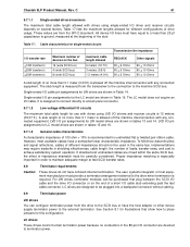
C 61 9.7.1.1 Single-ended drivers/receivers The maximum total cable length allowed with drives using single-ended I /O transfer rate Cheetah 9LP Product Manual, Rev. These values are from the SPI-2 document. All device I/O lines must have equal to or less than 25 pf capacitance to ground, measured at the beginning of drive usage. Table 17: Cable characteristics for different configurations of the stub . Table 17 lists the maximum lengths allowed for single-ended circuits Transmission line impedance I /O driver and receiver circuits depends on several factors.
C 61 9.7.1.1 Single-ended drivers/receivers The maximum total cable length allowed with drives using single-ended I /O transfer rate Cheetah 9LP Product Manual, Rev. These values are from the SPI-2 document. All device I/O lines must have equal to or less than 25 pf capacitance to ground, measured at the beginning of drive usage. Table 17: Cable characteristics for different configurations of the stub . Table 17 lists the maximum lengths allowed for single-ended circuits Transmission line impedance I /O driver and receiver circuits depends on several factors.
Product Manual
Page 81
...surface stiffness 37 MR heads 5 MTBF 13, 14, 22 multimode drivers and receivers 7 multiple segment 11 multi-segmented cache control 10 N ... 24, 26 operating environment 14 operating option 31 operating parameter 44 Cheetah 9LP Product Manual, Rev. C 71 host 12, 29, 35,... I/O signal 31 host system 31 host system malfunction 13 host/drive operational interface 13 hot plug 7, 15 humidity 22, 23 I...installation guide 8 installation instructions 31 instantaneous current peak 19 integrated Ultra1/Ultra2 SCSI controller 7 interface cable length 52 interface data 9 interface requirements 39 interface ...
...surface stiffness 37 MR heads 5 MTBF 13, 14, 22 multimode drivers and receivers 7 multiple segment 11 multi-segmented cache control 10 N ... 24, 26 operating environment 14 operating option 31 operating parameter 44 Cheetah 9LP Product Manual, Rev. C 71 host 12, 29, 35,... I/O signal 31 host system 31 host system malfunction 13 host/drive operational interface 13 hot plug 7, 15 humidity 22, 23 I...installation guide 8 installation instructions 31 instantaneous current peak 19 integrated Ultra1/Ultra2 SCSI controller 7 interface cable length 52 interface data 9 interface requirements 39 interface ...
Product Manual
Page 83
Cheetah 9LP Product Manual, Rev. C 73 SCSI interface cable 50 SCSI interface commands supported 40 SCSI interface connector 48 SCSI interface data 9 SCSI Interface Product Manual 3, 4, 5 SCSI systems error 30 SCSI systems error consideration 29 SCSI systems error management 30 SCSI-1 mode 40 SCSI-2/SCSI-3 45 SCSI-2/SCSI-3 mode 40 SE 59 Seagate ... shock 24 and vibration 24 shock mount 37 signal ground 37 single unit shipping pack 8 single-ended (SE) drivers and receivers 7 single-ended interface circuit 22 site installation 15 software interleave 12 spare part 15 spindle 20 spindle ...
Cheetah 9LP Product Manual, Rev. C 73 SCSI interface cable 50 SCSI interface commands supported 40 SCSI interface connector 48 SCSI interface data 9 SCSI Interface Product Manual 3, 4, 5 SCSI systems error 30 SCSI systems error consideration 29 SCSI systems error management 30 SCSI-1 mode 40 SCSI-2/SCSI-3 45 SCSI-2/SCSI-3 mode 40 SE 59 Seagate ... shock 24 and vibration 24 shock mount 37 signal ground 37 single unit shipping pack 8 single-ended (SE) drivers and receivers 7 single-ended interface circuit 22 site installation 15 software interleave 12 spare part 15 spindle 20 spindle ...


