Barracuda 7200.10 SATA Product Manual
Page 3
commands 54 5.0 Seagate Technology support services 55 Barracuda 7200.10 Serial ATA Product Manual, Rev. Contents 1.0 Introduction 1 1.1 About the Serial ATA interface 2 2.0 Drive specifications 3 2.1 Specification summary tables 3 2.2 Formatted capacity 26 2.2.1 LBA ...41 3.2 Configuring the drive 42 3.3 Serial ATA cables and connectors 42 3.4 Drive mounting 43 4.0 Serial ATA (SATA) interface 45 4.1 Hot-Plug compatibility 45 4.2 Serial ATA device plug connector pin definitions 46 4.3 Supported ATA commands 47 4.3.1 Identify Device command 49 4.3.2 Set Features command 53 4.3.3...
commands 54 5.0 Seagate Technology support services 55 Barracuda 7200.10 Serial ATA Product Manual, Rev. Contents 1.0 Introduction 1 1.1 About the Serial ATA interface 2 2.0 Drive specifications 3 2.1 Specification summary tables 3 2.2 Formatted capacity 26 2.2.1 LBA ...41 3.2 Configuring the drive 42 3.3 Serial ATA cables and connectors 42 3.4 Drive mounting 43 4.0 Serial ATA (SATA) interface 45 4.1 Hot-Plug compatibility 45 4.2 Serial ATA device plug connector pin definitions 46 4.3 Supported ATA commands 47 4.3.1 Identify Device command 49 4.3.2 Set Features command 53 4.3.3...
Barracuda 7200.10 SATA Product Manual
Page 8
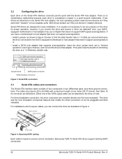
... a set any jumpers or other configuration options. • Thinner and more flexible cabling for improved enclosure airflow and ease of emulating parallel ATA device behavior to host software as a Device 0 (master) and Device 1 (slave) accessed at the same set of your current system and expect all emulated. It is not necessary to set of...
... a set any jumpers or other configuration options. • Thinner and more flexible cabling for improved enclosure airflow and ease of emulating parallel ATA device behavior to host software as a Device 0 (master) and Device 1 (slave) accessed at the same set of your current system and expect all emulated. It is not necessary to set of...
Barracuda 7200.10 SATA Product Manual
Page 32
... track 63 LBA mode When addressing these drives in LBA mode, all blocks (sectors) are consecutively numbered from 0 to hard drive capacity. See Section 4.3.1, "Identify Device command" (words 60-61 and 100-103) for additional information about 48bit addressing support of drives with capacities over 137 Gbytes. 2.3 Default logical geometry Cylinders... LBA mode, all blocks (sectors) are consecutively numbered from 0 to n-1, where n is the number of guaranteed sectors as defined above . 26 Barracuda 7200.10 Serial ATA Product Manual, Rev.
... track 63 LBA mode When addressing these drives in LBA mode, all blocks (sectors) are consecutively numbered from 0 to hard drive capacity. See Section 4.3.1, "Identify Device command" (words 60-61 and 100-103) for additional information about 48bit addressing support of drives with capacities over 137 Gbytes. 2.3 Default logical geometry Cylinders... LBA mode, all blocks (sectors) are consecutively numbered from 0 to n-1, where n is the number of guaranteed sectors as defined above . 26 Barracuda 7200.10 Serial ATA Product Manual, Rev.

Barracuda 7200.10 SATA Product Manual
Page 44
... by turning the equipment on different branch outlets. Radio and television interference. If this device in a residential installation. Refer to radio and television reception. Seagate has tested this equipment does cause interference to radio or television, which can be a...00345-4. 38 Barracuda 7200.10 Serial ATA Product Manual, Rev. These drives have the C-Tick marking, they comply with the manufacturer's instructions, may find helpful the following corrective measures: • Reorient the receiving antenna. • Move the device to the customer.
... by turning the equipment on different branch outlets. Radio and television interference. If this device in a residential installation. Refer to radio and television reception. Seagate has tested this equipment does cause interference to radio or television, which can be a...00345-4. 38 Barracuda 7200.10 Serial ATA Product Manual, Rev. These drives have the C-Tick marking, they comply with the manufacturer's instructions, may find helpful the following corrective measures: • Reorient the receiving antenna. • Move the device to the customer.
Barracuda 7200.10 SATA Product Manual
Page 48
... as if they are Device 0 (master) devices. The cable size may use a chipset that adapter. Attaching SATA cabling Each cable is keyed to -point with a maximum length of the SATA signal cable can connect the drive as shown in Figure 4. Barracuda 7200.10 Serial ATA drives support latching SATA ...error, your SATAequipped motherboard or host adapter may be 30 to 26 AWG with the Serial ATA host adapter. Either end of one Serial ATA host adapter, the host operating system views the two devices as if they were both "masters" on the drive for proper operation; If you can...
... as if they are Device 0 (master) devices. The cable size may use a chipset that adapter. Attaching SATA cabling Each cable is keyed to -point with a maximum length of the SATA signal cable can connect the drive as shown in Figure 4. Barracuda 7200.10 Serial ATA drives support latching SATA ...error, your SATAequipped motherboard or host adapter may be 30 to 26 AWG with the Serial ATA host adapter. Either end of one Serial ATA host adapter, the host operating system views the two devices as if they were both "masters" on the drive for proper operation; If you can...

Barracuda 7200.10 SATA Product Manual
Page 52
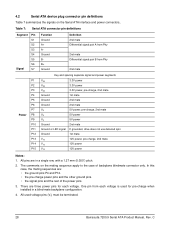
4.2 Serial ATA device plug connector pin definitions Table 15 summarizes the signals on the mating sequence apply to the case of the power pins. 3. All pins are three power pins for pre-charge when installed in a single row, with a 1.27 mm (0.050") pitch. 2. K Table 15: Serial ATA connector pin definitions Segment... and the other ground pins. • the signal pins and the rest of backplane blindmate connector only. The comments on the Serial ATA interface and power connectors.. All used for each voltage is used voltage pins (Vx) must be terminated. 46 Barracuda 7200.10 Serial...
4.2 Serial ATA device plug connector pin definitions Table 15 summarizes the signals on the mating sequence apply to the case of the power pins. 3. All pins are three power pins for pre-charge when installed in a single row, with a 1.27 mm (0.050") pitch. 2. K Table 15: Serial ATA connector pin definitions Segment... and the other ground pins. • the signal pins and the rest of backplane blindmate connector only. The comments on the Serial ATA interface and power connectors.. All used for each voltage is used voltage pins (Vx) must be terminated. 46 Barracuda 7200.10 Serial...

Barracuda 7200.10 SATA Product Manual
Page 53
implementation. Table 16: Supported ATA commands Command name Check Power Mode Device Configuration Freeze Lock Device Configuration Identify Device Configuration Restore Device Configuration Set Device Reset Download Microcode Execute Device Diagnostics Flush Cache Flush Cache Extended Format Track Identify Device Idle Idle Immediate Initialize Device Parameters Read Buffer Read DMA Read DMA Extended Read DMA Without Retries Read Log Ext...
implementation. Table 16: Supported ATA commands Command name Check Power Mode Device Configuration Freeze Lock Device Configuration Identify Device Configuration Restore Device Configuration Set Device Reset Download Microcode Execute Device Diagnostics Flush Cache Flush Cache Extended Format Track Identify Device Idle Idle Immediate Initialize Device Parameters Read Buffer Read DMA Read DMA Extended Read DMA Without Retries Read Log Ext...

Barracuda 7200.11 SATA Product Manual
Page 3
Contents 1.0 Introduction 1 1.1 About the Serial ATA interface 2 2.0 Drive specifications 3 2.1 Formatted capacity 10 2.1.1 LBA mode 10 2.2 Default logical geometry 10 2.3 Recording and interface technology 10 ...the drive 22 3.3 Serial ATA cables and connectors 23 3.4 Drive mounting 24 4.0 Serial ATA (SATA) interface 27 4.1 Hot-Plug compatibility 27 4.2 Serial ATA device plug connector pin definitions 28 4.3 Supported ATA commands 29 4.3.1 Identify Device command 31 4.3.2 Set Features command 35 4.3.3 S.M.A.R.T. E i commands 36 5.0 Seagate Technology support services 37 ...
Contents 1.0 Introduction 1 1.1 About the Serial ATA interface 2 2.0 Drive specifications 3 2.1 Formatted capacity 10 2.1.1 LBA mode 10 2.2 Default logical geometry 10 2.3 Recording and interface technology 10 ...the drive 22 3.3 Serial ATA cables and connectors 23 3.4 Drive mounting 24 4.0 Serial ATA (SATA) interface 27 4.1 Hot-Plug compatibility 27 4.2 Serial ATA device plug connector pin definitions 28 4.3 Supported ATA commands 29 4.3.1 Identify Device command 31 4.3.2 Set Features command 35 4.3.3 S.M.A.R.T. E i commands 36 5.0 Seagate Technology support services 37 ...

Barracuda 7200.11 SATA Product Manual
Page 8
... installation and configuration with Serial ATA devices like Device 0 devices. All Serial ATA devices behave like there is with existing host systems and software. 1.1 About the Serial ATA interface The Serial ATA interface provides several advantages over the traditional (parallel) ATA interface. Serial ATA was designed to allow you to install a Serial ATA host adapter and Serial ATA disc drive in a point...
... installation and configuration with Serial ATA devices like Device 0 devices. All Serial ATA devices behave like there is with existing host systems and software. 1.1 About the Serial ATA interface The Serial ATA interface provides several advantages over the traditional (parallel) ATA interface. Serial ATA was designed to allow you to install a Serial ATA host adapter and Serial ATA disc drive in a point...

Barracuda 7200.11 SATA Product Manual
Page 34
... signal pair B from each voltage. All used for each voltage is used voltage pins (Vx) must be terminated. 28 Barracuda 7200.11 Serial ATA Product Manual, Rev. All pins are three power pins for pre-charge when installed in a single row, with a 1.27 mm (0.050") pitch...P15 V12 12V power, pre-charge, 2nd mate 12V power 12V power Notes: 1. There are in a blind-mate backplane configuration. 4. 4.2 Serial ATA device plug connector pin definitions Table 8 summarizes the signals on the mating sequence apply to the case of the power pins. 3. The comments on the Serial...
... signal pair B from each voltage. All used for each voltage is used voltage pins (Vx) must be terminated. 28 Barracuda 7200.11 Serial ATA Product Manual, Rev. All pins are three power pins for pre-charge when installed in a single row, with a 1.27 mm (0.050") pitch...P15 V12 12V power, pre-charge, 2nd mate 12V power 12V power Notes: 1. There are in a blind-mate backplane configuration. 4. 4.2 Serial ATA device plug connector pin definitions Table 8 summarizes the signals on the mating sequence apply to the case of the power pins. 3. The comments on the Serial...

Barracuda 7200.11 SATA Product Manual
Page 3
commands 34 5.0 Seagate Technology support services 35 Barracuda 7200.11 Serial ATA Product Manual, Rev. Contents 1.0 Introduction 1 1.1 About the Serial ATA interface 2 2.0 Drive specifications 3 2.1 Formatted capacity 10 2.1.1 LBA mode 10 2.2 Default logical ... 21 3.2 Configuring the drive 22 3.3 Serial ATA cables and connectors 22 3.4 Drive mounting 23 4.0 Serial ATA (SATA) interface 25 4.1 Hot-Plug compatibility 25 4.2 Serial ATA device plug connector pin definitions 26 4.3 Supported ATA commands 27 4.3.1 Identify Device command 29 4.3.2 Set Features command 33 4.3.3 ...
commands 34 5.0 Seagate Technology support services 35 Barracuda 7200.11 Serial ATA Product Manual, Rev. Contents 1.0 Introduction 1 1.1 About the Serial ATA interface 2 2.0 Drive specifications 3 2.1 Formatted capacity 10 2.1.1 LBA mode 10 2.2 Default logical ... 21 3.2 Configuring the drive 22 3.3 Serial ATA cables and connectors 22 3.4 Drive mounting 23 4.0 Serial ATA (SATA) interface 25 4.1 Hot-Plug compatibility 25 4.2 Serial ATA device plug connector pin definitions 26 4.3 Supported ATA commands 27 4.3.1 Identify Device command 29 4.3.2 Set Features command 33 4.3.3 ...

Barracuda 7200.11 SATA Product Manual
Page 8
...8226; Scalability to host software where two devices on two separate ports. There is no master/slave relationship with Serial ATA devices like Device 0 devices. Serial ATA was designed to allow you to install a Serial ATA host adapter and Serial ATA disc drive in a point-to host software... as if they were both drives behave as a Device 0 (master) and Device 1 (slave) accessed at ...
...8226; Scalability to host software where two devices on two separate ports. There is no master/slave relationship with Serial ATA devices like Device 0 devices. Serial ATA was designed to allow you to install a Serial ATA host adapter and Serial ATA disc drive in a point-to host software... as if they were both drives behave as a Device 0 (master) and Device 1 (slave) accessed at ...

Barracuda 7200.11 SATA Product Manual
Page 32
... power 2nd mate P11 Ground or LED signal If grounded, drive does not use deferred spin P12 Ground 1st mate. The comments on the Serial ATA interface and power connectors.. G In this case, the mating sequences are three power pins for pre-charge when installed in a single row, with a 1.27 ... P12. • the pre-charge power pins and the other ground pins. • the signal pins and the rest of backplane blindmate connector only. 4.2 Serial ATA device plug connector pin definitions Table 7 summarizes the signals on the mating sequence apply to the case of the power pins. 3.
... power 2nd mate P11 Ground or LED signal If grounded, drive does not use deferred spin P12 Ground 1st mate. The comments on the Serial ATA interface and power connectors.. G In this case, the mating sequences are three power pins for pre-charge when installed in a single row, with a 1.27 ... P12. • the pre-charge power pins and the other ground pins. • the signal pins and the rest of backplane blindmate connector only. 4.2 Serial ATA device plug connector pin definitions Table 7 summarizes the signals on the mating sequence apply to the case of the power pins. 3.

Barracuda SATA Product Manual
Page 3
Contents Seagate Technology Support Services 7 1.0 Introduction 9 1.1 About the Serial ATA interface 9 2.0 Drive Specifications 11 2.1 Specification summary tables 11 2.2 Formatted capacity 15 2.2.1 LBA mode 16 2.3 Default ...discharge precautions 27 3.2 Configuring the drive 27 3.3 Serial ATA cables and connectors 27 3.4 Drive mounting 28 4.0 Serial ATA (SATA) Interface 31 4.1 Hot-Plug compatibility 31 4.2 Serial ATA device plug connector pin definitions 31 4.3 Supported ATA commands 32 4.3.1 Identify Device command 35 4.3.2 Set Features command 39 4.3.3 S.M.A.R.T. commands...
Contents Seagate Technology Support Services 7 1.0 Introduction 9 1.1 About the Serial ATA interface 9 2.0 Drive Specifications 11 2.1 Specification summary tables 11 2.2 Formatted capacity 15 2.2.1 LBA mode 16 2.3 Default ...discharge precautions 27 3.2 Configuring the drive 27 3.3 Serial ATA cables and connectors 27 3.4 Drive mounting 28 4.0 Serial ATA (SATA) Interface 31 4.1 Hot-Plug compatibility 31 4.2 Serial ATA device plug connector pin definitions 31 4.3 Supported ATA commands 32 4.3.1 Identify Device command 35 4.3.2 Set Features command 39 4.3.3 S.M.A.R.T. commands...
Barracuda SATA Product Manual
Page 9
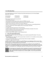
...drive returns. • Support for S.M.A.R.T. In addition, Serial ATA makes the transition from parallel ATA easy by providing legacy software support. There is no master/slave relationship with Serial ATA devices like there is not necessary to set of host bus ...behave as normal. 1.0 Introduction This manual describes the functional, mechanical and interface specifications for the following Seagate Barracuda® model drives: ST31000524AS ST3750525AS ST3500413AS ST3320413AS ST3250312AS ST3160316AS These drives provide the following key features: • 7200 RPM spindle speed. &#...
...drive returns. • Support for S.M.A.R.T. In addition, Serial ATA makes the transition from parallel ATA easy by providing legacy software support. There is no master/slave relationship with Serial ATA devices like there is not necessary to set of host bus ...behave as normal. 1.0 Introduction This manual describes the functional, mechanical and interface specifications for the following Seagate Barracuda® model drives: ST31000524AS ST3750525AS ST3500413AS ST3320413AS ST3250312AS ST3160316AS These drives provide the following key features: • 7200 RPM spindle speed. &#...

Barracuda SATA Product Manual
Page 10
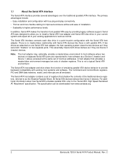
...seagate.com The Serial ATA host adapter and drive share the function of the traditional device registers, referred to as the Shadow Register Block. The specification can be downloaded from www.sata-io.org. 10 Barracuda SATA Product Manual, Rev. B All Serial ATA devices behave like Device 0 devices.... The Command and Control Block registers, PIO and DMA data transfers, resets, and interrupts are all emulated. The Serial ATA host adapter contains a set of registers that shadow the contents...
...seagate.com The Serial ATA host adapter and drive share the function of the traditional device registers, referred to as the Shadow Register Block. The specification can be downloaded from www.sata-io.org. 10 Barracuda SATA Product Manual, Rev. B All Serial ATA devices behave like Device 0 devices.... The Command and Control Block registers, PIO and DMA data transfers, resets, and interrupts are all emulated. The Serial ATA host adapter contains a set of registers that shadow the contents...

Barracuda SATA Product Manual
Page 31
... S1 Ground 2nd mate S2 A+ Differential signal pair A from www.serialata.org. 4.2 Serial ATA device plug connector pin definitions Table 8 summarizes the signals on the Serial ATA interface and power connectors. S4 Ground 2nd mate S5 B- This specification can be downloaded from ...Phy S3 A- B 31 For detailed information about the Serial ATA interface, refer to the "Serial ATA: High Speed Serialized AT Attachment" specification. 4.1 Hot-Plug compatibility Barracuda drives incorporate connectors which enable you to 6....
... S1 Ground 2nd mate S2 A+ Differential signal pair A from www.serialata.org. 4.2 Serial ATA device plug connector pin definitions Table 8 summarizes the signals on the Serial ATA interface and power connectors. S4 Ground 2nd mate S5 B- This specification can be downloaded from ...Phy S3 A- B 31 For detailed information about the Serial ATA interface, refer to the "Serial ATA: High Speed Serialized AT Attachment" specification. 4.1 Hot-Plug compatibility Barracuda drives incorporate connectors which enable you to 6....

Barracuda 7200.9 SATA Product Manual
Page 3
Contents 1.0 Introduction 1 1.1 About the Serial ATA interface 2 2.0 Drive specifications 3 2.1 Specification summary tables 3 2.2 Formatted capacity 10 2.2.1 LBA mode 10 2.3 Default logical geometry 10 2.4 ... drive 24 3.3 Serial ATA cables and connectors 24 3.4 Drive mounting 25 4.0 Serial ATA (SATA) interface 27 4.1 Hot-Plug compatibility 27 4.2 Serial ATA device plug connector pin definitions 28 4.3 Supported ATA commands 29 4.3.1 Identify Device command 31 4.3.2 Set Features command 34 4.3.3 S.M.A.R.T. commands 35 5.0 Seagate Technology support services 37 Barracuda...
Contents 1.0 Introduction 1 1.1 About the Serial ATA interface 2 2.0 Drive specifications 3 2.1 Specification summary tables 3 2.2 Formatted capacity 10 2.2.1 LBA mode 10 2.3 Default logical geometry 10 2.4 ... drive 24 3.3 Serial ATA cables and connectors 24 3.4 Drive mounting 25 4.0 Serial ATA (SATA) interface 27 4.1 Hot-Plug compatibility 27 4.2 Serial ATA device plug connector pin definitions 28 4.3 Supported ATA commands 29 4.3.1 Identify Device command 31 4.3.2 Set Features command 34 4.3.3 S.M.A.R.T. commands 35 5.0 Seagate Technology support services 37 Barracuda...
Barracuda 7200.9 SATA Product Manual
Page 8
... There is no master/slave relationship with Serial ATA devices like Device 0 devices. A host adapter that shadow the contents of shadow registers. The Serial ATA interface connects each disc drive in your existing applications to the "Serial ATA: High Speed Serialized AT Attachment" specification. This... essentially means both drives behave as the Shadow Register Block. The Serial ATA host adapter and drive share the function of emulating parallel ATA device behavior to -point configuration with true plug-and-play connectivity. • Thinner and more...
... There is no master/slave relationship with Serial ATA devices like Device 0 devices. A host adapter that shadow the contents of shadow registers. The Serial ATA interface connects each disc drive in your existing applications to the "Serial ATA: High Speed Serialized AT Attachment" specification. This... essentially means both drives behave as the Shadow Register Block. The Serial ATA host adapter and drive share the function of emulating parallel ATA device behavior to -point configuration with true plug-and-play connectivity. • Thinner and more...
Barracuda 7200.9 SATA Product Manual
Page 34
...pair A from Phy 2nd mate Differential signal pair B from each voltage is used voltage pins (Vx) must be terminated. 28 Barracuda 7200.9 Serial ATA Product Manual, Rev. In this case, the mating sequences are: • the ground pins P4 and P12. • the pre-charge power pins.... • the signal pins and the rest of backplane blindmate connector only. The comments on the Serial ATA interface and power connectors.. All used for each voltage. 4.2 Serial ATA device plug connector pin definitions Table 7 summarizes the signals on the mating sequence apply to the case of the ...
...pair A from Phy 2nd mate Differential signal pair B from each voltage is used voltage pins (Vx) must be terminated. 28 Barracuda 7200.9 Serial ATA Product Manual, Rev. In this case, the mating sequences are: • the ground pins P4 and P12. • the pre-charge power pins.... • the signal pins and the rest of backplane blindmate connector only. The comments on the Serial ATA interface and power connectors.. All used for each voltage. 4.2 Serial ATA device plug connector pin definitions Table 7 summarizes the signals on the mating sequence apply to the case of the ...


