Product Manual
Page 5
... 2.14.2 Electromagnetic compatibility 18 2.14.3 FCC verification 19 3.0 Configuring and mounting the drive 21 3.1 Handling and static discharge precautions 21 3.2 Breather filter hole precautions 22 3.3 Jumper settings 23 3.3.1 Master/slave configuration 23 3.3.2 Cable select option 23 3.3.3 Ultra ATA/100 cable 24 3.4 Drive mounting 24 4.0 ATA interface 27 4.1 ATA interface signals and connector...
... 2.14.2 Electromagnetic compatibility 18 2.14.3 FCC verification 19 3.0 Configuring and mounting the drive 21 3.1 Handling and static discharge precautions 21 3.2 Breather filter hole precautions 22 3.3 Jumper settings 23 3.3.1 Master/slave configuration 23 3.3.2 Cable select option 23 3.3.3 Ultra ATA/100 cable 24 3.4 Drive mounting 24 4.0 ATA interface 27 4.1 ATA interface signals and connector...

Product Manual
Page 7
Barracuda 5400.1 Product Manual, Rev. Typical 5V startup and operation current profile 11 Typical 12V startup and operation current profile 11 Breather filter hole location 22 Master/slave jumper settings 23 Ultra ATA cable connectors 24 Mounting dimensions-top, side and end view 25 I/O pins and supported ATA signals 28 F v List of Figures Figure 1. Figure 4. Figure 7. Figure 5. Figure 2. Figure 6. Figure 3.
Barracuda 5400.1 Product Manual, Rev. Typical 5V startup and operation current profile 11 Typical 12V startup and operation current profile 11 Breather filter hole location 22 Master/slave jumper settings 23 Ultra ATA cable connectors 24 Mounting dimensions-top, side and end view 25 I/O pins and supported ATA signals 28 F v List of Figures Figure 1. Figure 4. Figure 7. Figure 5. Figure 2. Figure 6. Figure 3.
Product Manual
Page 31
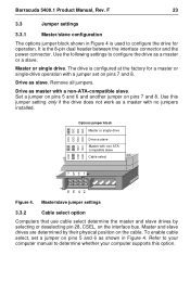
...master with non ATAcompatible slave Cable select 7531 8642 Figure 4. Refer to your computer supports this jumper setting only if the drive does not work as a master with a jumper set a jumper on the cable. Drive as shown in Figure 4 is the 8-pin dual header between ...the interface connector and the power connector. Remove all jumpers. F 23 3.3 Jumper settings 3.3.1 Master/slave configuration The options jumper block shown in Figure 4. To enable cable select, set on pins 7 and 8. Use the following settings to configure the drive as slave. It is used to...
...master with non ATAcompatible slave Cable select 7531 8642 Figure 4. Refer to your computer supports this jumper setting only if the drive does not work as a master with a jumper set a jumper on the cable. Drive as shown in Figure 4 is the 8-pin dual header between ...the interface connector and the power connector. Remove all jumpers. F 23 3.3 Jumper settings 3.3.1 Master/slave configuration The options jumper block shown in Figure 4. To enable cable select, set on pins 7 and 8. Use the following settings to configure the drive as slave. It is used to...
Product Manual
Page 54
... Information Technology Equipment 18 Initialize Device Parameters 29 interface 7, 27 interface signals 27 interference 19 interleave 7 internal data-transfer rate OD 7 ISO document 7779 16 J jumper settings 23 K Korean RRL 18 L LBA mode 6 length 7 logical geometry 6 M maintenance 17 master 23 master/slave 1 Master/slave configuration 23 maximum temperature 13 Mean time between...
... Information Technology Equipment 18 Initialize Device Parameters 29 interface 7, 27 interface signals 27 interference 19 interleave 7 internal data-transfer rate OD 7 ISO document 7779 16 J jumper settings 23 K Korean RRL 18 L LBA mode 6 length 7 logical geometry 6 M maintenance 17 master 23 master/slave 1 Master/slave configuration 23 maximum temperature 13 Mean time between...

