Product Manual
Page 5
B FCC verification 15 Configuring and mounting the drive 17 Handling and static-discharge precautions 17 Jumper settings 18 Master/slave configuration 18 Cable-select option 19 Ultra ATA/66 cable 19 Drive mounting 19 ATA interface 21 ATA interface signals and connector pins 21 Supported ATA commands 23 Identify Drive command 24 Set Features command 29 S.M.A.R.T. commands 30 iv U8 Family Product Manual, Rev.
B FCC verification 15 Configuring and mounting the drive 17 Handling and static-discharge precautions 17 Jumper settings 18 Master/slave configuration 18 Cable-select option 19 Ultra ATA/66 cable 19 Drive mounting 19 ATA interface 21 ATA interface signals and connector pins 21 Supported ATA commands 23 Identify Drive command 24 Set Features command 29 S.M.A.R.T. commands 30 iv U8 Family Product Manual, Rev.
Product Manual
Page 8
... It also includes installation instructions and jumper settings. These drives provide the following key features: • Low power consumption • Quiet operation • High instantaneous (burst) data-transfer rates (up to 66.6 Mbytes per second) using Ultra DMA mode 4 • 8.9 msec seek time, 5,...400-RPM and 512-Kbyte buffer combine for excellent desktop performance • 350 Gs nonoperating shock • GMR recording heads and EPRML technology, which provide the drives with increased areal density •...
... It also includes installation instructions and jumper settings. These drives provide the following key features: • Low power consumption • Quiet operation • High instantaneous (burst) data-transfer rates (up to 66.6 Mbytes per second) using Ultra DMA mode 4 • 8.9 msec seek time, 5,...400-RPM and 512-Kbyte buffer combine for excellent desktop performance • 350 Gs nonoperating shock • GMR recording heads and EPRML technology, which provide the drives with increased areal density •...

Product Manual
Page 9
...) 1.5 (read) 2.1 (write) Average seek time (msec typical) 8.9 2 U8 Family Product Manual, Rev. B Specification summary table The specifications listed in this manual. Drive Specification ST317221A ST313021A ST38410A ST34313A Guaranteed Mbytes (×106 bytes) 17,245 13,022 8,622 4,327 Guaranteed sectors 33,683,328 25,434,228 16...(Mbits/ sec max) 285.5 I/O data-transfer rate (Mbytes/ sec max) 66.6 ATA data-transfer modes supported PIO modes 0-4 Multiword DMA modes 0-2 Ultra DMA modes 0-4 Cache buffer (Kbytes) 512 256-Kbyte cache is optional for quick reference.
...) 1.5 (read) 2.1 (write) Average seek time (msec typical) 8.9 2 U8 Family Product Manual, Rev. B Specification summary table The specifications listed in this manual. Drive Specification ST317221A ST313021A ST38410A ST34313A Guaranteed Mbytes (×106 bytes) 17,245 13,022 8,622 4,327 Guaranteed sectors 33,683,328 25,434,228 16...(Mbits/ sec max) 285.5 I/O data-transfer rate (Mbytes/ sec max) 66.6 ATA data-transfer modes supported PIO modes 0-4 Multiword DMA modes 0-2 Ultra DMA modes 0-4 Cache buffer (Kbytes) 512 256-Kbyte cache is optional for quick reference.

Product Manual
Page 13
The specifications in the table below are measured using drive diagnostics. 6 U8 Family Product Manual, Rev. All times are defined as follows: B 1.3 Recording and interface technology Interface ATA Recording method...400 Internal data-transfer rate (Mbits/sec max) 285.5 I/O data-transfer rate (Mbytes/sec max) 16.6 (PIO mode 4) 66.6 (Ultra DMA mode 4) Interleave 1:1 Cache buffer (Kbytes) 512 256 (ST34313A) 1.4 Physical characteristics Drive Specification Maximum height Maximum width Maximum length Typical weight (mm) (inches) (mm) (inches) (mm) (inches) (grams) (pounds) ...
The specifications in the table below are measured using drive diagnostics. 6 U8 Family Product Manual, Rev. All times are defined as follows: B 1.3 Recording and interface technology Interface ATA Recording method...400 Internal data-transfer rate (Mbits/sec max) 285.5 I/O data-transfer rate (Mbytes/sec max) 16.6 (PIO mode 4) 66.6 (Ultra DMA mode 4) Interleave 1:1 Cache buffer (Kbytes) 512 256 (ST34313A) 1.4 Physical characteristics Drive Specification Maximum height Maximum width Maximum length Typical weight (mm) (inches) (mm) (inches) (mm) (inches) (grams) (pounds) ...
Product Manual
Page 26
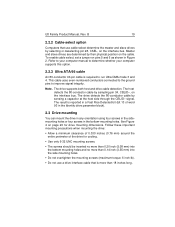
B 19 2.2.2 Cable-select option Computers that use a drive interface cable that is required to run Ultra DMA mode 3 and 4. Master and slave drives are determined by selecting or deselecting pin 28, CSEL, on the cable. The host detects the 80-conductor cable by sensing a capacitor at ...manual to improve signal integrity. This cable uses even-numbered conductors connected to the ground pins to determine whether your computer supports this option. 2.2.3 Ultra ATA/66 cable An 80-conductor 40-pin cable is more than 18 inches long. The result is reported in a Fast Rise Detected bit ...
B 19 2.2.2 Cable-select option Computers that use a drive interface cable that is required to run Ultra DMA mode 3 and 4. Master and slave drives are determined by selecting or deselecting pin 28, CSEL, on the cable. The host detects the 80-conductor cable by sensing a capacitor at ...manual to improve signal integrity. This cable uses even-numbered conductors connected to the ground pins to determine whether your computer supports this option. 2.2.3 Ultra ATA/66 cable An 80-conductor 40-pin cable is more than 18 inches long. The result is reported in a Fast Rise Detected bit ...
Product Manual
Page 28
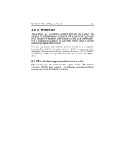
.... It supports ATA programmed input/output (PIO) modes 0-4; The drive also supports the use of AT Attachment with Packet Interface Extension (ATA/ATAPI-5), NCITS T13 1153D, subsequently referred to provide reliable high-speed data transfers. multiword DMA modes 0-2, and Ultra DMA modes 0-4. For detailed information about the ATA interface, refer ... a detailed description of these signals, refer to a single AT host bus. You can use the industry-standard ATA task file interface that the drive supports. B 21 3.0 ATA interface These drives use a daisy-chain cable to connect two...
.... It supports ATA programmed input/output (PIO) modes 0-4; The drive also supports the use of AT Attachment with Packet Interface Extension (ATA/ATAPI-5), NCITS T13 1153D, subsequently referred to provide reliable high-speed data transfers. multiword DMA modes 0-2, and Ultra DMA modes 0-4. For detailed information about the ATA interface, refer ... a detailed description of these signals, refer to a single AT host bus. You can use the industry-standard ATA task file interface that the drive supports. B 21 3.0 ATA interface These drives use a daisy-chain cable to connect two...

Product Manual
Page 29
...:0) 19 Ground 20 (No Pin) 21 DMA Request 22 Ground 23 Device I/O Write: Stop Ultra DMA Burst 24 Ground 25 Device I/O Read: Host Ultra DMA Ready: Host Ultra DMA Data Strobe 26 Ground 27 I /O pins and supported ATA signals B Drive pin # 1 2 3 4 5 6 7 8 9 10 11 12 13 14 15 16 17 18 19 20 21 22... 23 24 25 26 27 28 29 30 31 32 33 34 35 36 37 38 39 40 Signal...
...:0) 19 Ground 20 (No Pin) 21 DMA Request 22 Ground 23 Device I/O Write: Stop Ultra DMA Burst 24 Ground 25 Device I/O Read: Host Ultra DMA Ready: Host Ultra DMA Data Strobe 26 Ground 27 I /O pins and supported ATA signals B Drive pin # 1 2 3 4 5 6 7 8 9 10 11 12 13 14 15 16 17 18 19 20 21 22... 23 24 25 26 27 28 29 30 31 32 33 34 35 36 37 38 39 40 Signal...

Product Manual
Page 34
... version number Minor version number Command sets supported Command sets supported Command sets support extension Command sets enabled Command sets enabled Command sets enable extension Ultra DMA support and current mode (see note following this table) Security erase time Enhanced security erase time 27 Value 0078H 0078H 00F0H 0078H 0000H 0000H...
... version number Minor version number Command sets supported Command sets supported Command sets support extension Command sets enabled Command sets enabled Command sets enable extension Ultra DMA support and current mode (see note following this table) Security erase time Enhanced security erase time 27 Value 0078H 0078H 00F0H 0078H 0000H 0000H...
Product Manual
Page 35
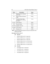
28 U8 Family Product Manual, Rev. Bit Word 88 0 Ultra DMA mode 0 is supported. 1 Ultra DMA mode 1 is supported. 2 Ultra DMA mode 2 is supported. 3 Ultra DMA mode 3 is currently active. See the bit descriptions below for words, 63, 88 and 93 of the Identify Drive data: Description (if bit is set to 1) Bit Word 63 0 Multiword... Password Revision code FFFEH 93 Hardware Reset Value (see description following this table) xxxxH 94-127 ATA-reserved 0000H 128 Security Status 0001H 129-159 Seagate-reserved xxxxH 160-254 ATA-reserved 0000H 255 Integrity word xxA5H Note.
28 U8 Family Product Manual, Rev. Bit Word 88 0 Ultra DMA mode 0 is supported. 1 Ultra DMA mode 1 is supported. 2 Ultra DMA mode 2 is supported. 3 Ultra DMA mode 3 is currently active. See the bit descriptions below for words, 63, 88 and 93 of the Identify Drive data: Description (if bit is set to 1) Bit Word 63 0 Multiword... Password Revision code FFFEH 93 Hardware Reset Value (see description following this table) xxxxH 94-127 ATA-reserved 0000H 128 Security Status 0001H 129-159 Seagate-reserved xxxxH 160-254 ATA-reserved 0000H 255 Integrity word xxA5H Note.

Product Manual
Page 36
...) 20H Multiword DMA mode 0 21H Multiword DMA mode 1 22H Multiword DMA mode 2 When the drive receives this command, it sets BSY, checks the contents of various features that the drive supports, the command is currently active. Power-on value in the register does not represent a feature... clears BSY and generates an interrupt. B 29 4 Ultra DMA mode 4 is supported. 8 Ultra DMA mode 0 is currently active. 9 Ultra DMA mode 1 is currently active. 10 Ultra DMA mode 2 is currently active. 11 Ultra DMA mode 3 is currently active. 12 Ultra DMA mode 4 is aborted. The acceptable values for ...
...) 20H Multiword DMA mode 0 21H Multiword DMA mode 1 22H Multiword DMA mode 2 When the drive receives this command, it sets BSY, checks the contents of various features that the drive supports, the command is currently active. Power-on value in the register does not represent a feature... clears BSY and generates an interrupt. B 29 4 Ultra DMA mode 4 is supported. 8 Ultra DMA mode 0 is currently active. 9 Ultra DMA mode 1 is currently active. 10 Ultra DMA mode 2 is currently active. 11 Ultra DMA mode 3 is currently active. 12 Ultra DMA mode 4 is aborted. The acceptable values for ...

Product Manual
Page 37
... on , or after a hardware or software reset, the default values of the features are predictable. This drive is enabled, the drive monitors predetermined drive attributes that a failure is limited to degradation over time. Read Data D1H Obsolete D2H S.M.A.R.T. Save Attribute Values... that the drive uses. Enable/Disable Attribute Autosave D3H S.M.A.R.T. commands and implementation, see the Draft ATA-5 Standard. Read Log Sector When S.M.A.R.T. to the host. B 40H Ultra DMA mode 0 41H Ultra DMA mode 1 42H Ultra DMA mode 2 43H Ultra DMA mode 3 44H Ultra DMA mode ...
... on , or after a hardware or software reset, the default values of the features are predictable. This drive is enabled, the drive monitors predetermined drive attributes that a failure is limited to degradation over time. Read Data D1H Obsolete D2H S.M.A.R.T. Save Attribute Values... that the drive uses. Enable/Disable Attribute Autosave D3H S.M.A.R.T. commands and implementation, see the Draft ATA-5 Standard. Read Log Sector When S.M.A.R.T. to the host. B 40H Ultra DMA mode 0 41H Ultra DMA mode 1 42H Ultra DMA mode 2 43H Ultra DMA mode 3 44H Ultra DMA mode ...