Product Manual
Page 5
commands 30 iv U8 Family Product Manual, Rev. B FCC verification 15 Configuring and mounting the drive 17 Handling and static-discharge precautions 17 Jumper settings 18 Master/slave configuration 18 Cable-select option 19 Ultra ATA/66 cable 19 Drive mounting 19 ATA interface 21 ATA interface signals and connector pins 21 Supported ATA commands 23 Identify Drive command 24 Set Features command 29 S.M.A.R.T.
commands 30 iv U8 Family Product Manual, Rev. B FCC verification 15 Configuring and mounting the drive 17 Handling and static-discharge precautions 17 Jumper settings 18 Master/slave configuration 18 Cable-select option 19 Ultra ATA/66 cable 19 Drive mounting 19 ATA interface 21 ATA interface signals and connector pins 21 Supported ATA commands 23 Identify Drive command 24 Set Features command 29 S.M.A.R.T.

Product Manual
Page 6
U8 Family Product Manual, Rev. B v Figures Typical startup and operation current profile 9 Master/slave jumper settings 18 Mounting dimensions-top, side and end view 20 I/O pins and supported ATA signals 22
U8 Family Product Manual, Rev. B v Figures Typical startup and operation current profile 9 Master/slave jumper settings 18 Mounting dimensions-top, side and end view 20 I/O pins and supported ATA signals 22
Product Manual
Page 8
...1 Introduction This manual describes the functional, mechanical and interface specifications for S.M.A.R.T. It also includes installation instructions and jumper settings. These drives provide the following key features: • Low power consumption • Quiet operation • High instantaneous ...recording heads and EPRML technology, which provide the drives with increased areal density • State-of master/slave drives that use cable select (CSEL) • SeaShield® innovative, shock-absorbing cover shields the drive against electrostatic discharge (ESD) and other handling ...
...1 Introduction This manual describes the functional, mechanical and interface specifications for S.M.A.R.T. It also includes installation instructions and jumper settings. These drives provide the following key features: • Low power consumption • Quiet operation • High instantaneous ...recording heads and EPRML technology, which provide the drives with increased areal density • State-of master/slave drives that use cable select (CSEL) • SeaShield® innovative, shock-absorbing cover shields the drive against electrostatic discharge (ESD) and other handling ...
Product Manual
Page 24
... pins or the printed circuit board. • Do not remove the factory-installed labels from the drive or cover them with care. Keep the drive in the SeaShell package until you are used to potential handling and electrostatic discharge (ESD) hazards. Do...the drive while it with additional labels. The design permits attaching cables, software loading and label/barcode scanning without removing the drive from electrostatic discharge (ESD) and minor impact damage. This minimizes handling damage. The soft SeaShield cover also includes installation instructions and jumper settings....
... pins or the printed circuit board. • Do not remove the factory-installed labels from the drive or cover them with care. Keep the drive in the SeaShell package until you are used to potential handling and electrostatic discharge (ESD) hazards. Do...the drive while it with additional labels. The design permits attaching cables, software loading and label/barcode scanning without removing the drive from electrostatic discharge (ESD) and minor impact damage. This minimizes handling damage. The soft SeaShield cover also includes installation instructions and jumper settings....

Product Manual
Page 25
... a master or single-drive operation with no jumpers installed. Remove all jumpers. 18 U8 Family Product Manual, Rev. Drive as a master or a slave. Options jumper block (J8) Master or single drive Drive is the 8-pin dual header between the interface connector and the power connector. Set a jumper on pins 5 and 6 and a jumper on pins 7 and 8. Drive as a master with a jumper set on pins...
... a master or single-drive operation with no jumpers installed. Remove all jumpers. 18 U8 Family Product Manual, Rev. Drive as a master or a slave. Options jumper block (J8) Master or single drive Drive is the 8-pin dual header between the interface connector and the power connector. Set a jumper on pins 5 and 6 and a jumper on pins 7 and 8. Drive as a master with a jumper set on pins...
Product Manual
Page 26
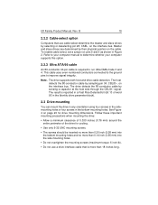
... computer supports this option. 2.2.3 Ultra ATA/66 cable An 80-conductor 40-pin cable is reported in a Fast Rise Detected bit (bit 13 of the drive for drive mounting dimensions. This cable uses even-numbered conductors connected to the ground pins to run Ultra DMA mode 3 and 4. The... that is more than 0.14 inch (3.55 mm) into the bottom mounting holes and no more than 18 inches long. Note. To enable cable select, set a jumper on the interface bus. See Figure 4 on page 20 for cooling. • Use only 6-32 UNC mounting screws. • The screws should be inserted no...
... computer supports this option. 2.2.3 Ultra ATA/66 cable An 80-conductor 40-pin cable is reported in a Fast Rise Detected bit (bit 13 of the drive for drive mounting dimensions. This cable uses even-numbered conductors connected to the ground pins to run Ultra DMA mode 3 and 4. The... that is more than 0.14 inch (3.55 mm) into the bottom mounting holes and no more than 18 inches long. Note. To enable cable select, set a jumper on the interface bus. See Figure 4 on page 20 for cooling. • Use only 6-32 UNC mounting screws. • The screws should be inserted no...

