Momentus Thin (.2-4K) SATA Product Manual
Page 3
D i Contents 1.0 Seagate Technology support services 1 2.0 Introduction 2 2.1 About the Serial ATA interface 3 3.0 Drive specifications 4 3.1 Specification summary table 4 3.2 Formatted capacity 6 3.2.1 LBA mode 6 3.3 Default logical geometry 6 ... static-discharge precautions 18 4.2 Configuring the drive 18 4.3 Serial ATA cables and connectors 19 4.4 Drive mounting 19 5.0 About FIPS 22 6.0 Serial ATA (SATA) interface 24 6.1 Hot-Plug compatibility 24 6.2 Serial ATA device plug connector pin definitions 24 6.3 Supported ATA commands 26 6.3.1 Identify Device command 28 6.3.2 ...
D i Contents 1.0 Seagate Technology support services 1 2.0 Introduction 2 2.1 About the Serial ATA interface 3 3.0 Drive specifications 4 3.1 Specification summary table 4 3.2 Formatted capacity 6 3.2.1 LBA mode 6 3.3 Default logical geometry 6 ... static-discharge precautions 18 4.2 Configuring the drive 18 4.3 Serial ATA cables and connectors 19 4.4 Drive mounting 19 5.0 About FIPS 22 6.0 Serial ATA (SATA) interface 24 6.1 Hot-Plug compatibility 24 6.2 Serial ATA device plug connector pin definitions 24 6.3 Supported ATA commands 26 6.3.1 Identify Device command 28 6.3.2 ...
Momentus Thin (.2-4K) SATA Product Manual
Page 5
List of FIPS tamper evidence labels 22 Momentus Thin Product Manual, Gen-2 Rev. Figure 2. Figure 3. top, side and end view 21 Example of Figures Figure 1. Figure 5. Figure 4. Figure 6. D iii top, side and end view 20 Mounting dimensions (for FIPS 140-2 models) - Typical +5V only startup and operation current profile 10 Serial ATA connectors 18 Attaching SATA cabling 19 Mounting dimensions (for standard models) -
List of FIPS tamper evidence labels 22 Momentus Thin Product Manual, Gen-2 Rev. Figure 2. Figure 3. top, side and end view 21 Example of Figures Figure 1. Figure 5. Figure 4. Figure 6. D iii top, side and end view 20 Mounting dimensions (for FIPS 140-2 models) - Typical +5V only startup and operation current profile 10 Serial ATA connectors 18 Attaching SATA cabling 19 Mounting dimensions (for standard models) -
Momentus Thin (.2-4K) SATA Product Manual
Page 10
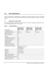
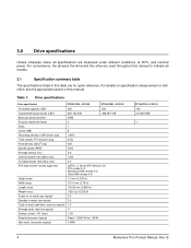
...summary table The specifications listed in this manual Table 1: Drive specifications Drive specification ST320LT007 - 9ZV142 ST320LT009 - 9WC142 ST320LT011 - 9ZVG42 ST320LT014 - 9YK142 ST250LT007 - 9ZV14C ST250LT009 - 9WC14C ST250LT011 - 9ZVG4C ST250LT014 - 9YK14C Formatted capacity (GB)* 320 250 Guaranteed logical blocks...latency (ms) 4.17 Internal transfer rate (Mb/s max) 1247 I/O data transfer rate (Gb/s max) 3.0 ATA data-transfer modes supported SATA 1.0, Serial ATA Revision 2.6 PIO modes 0-4 Multiword DMA modes 0-2 Ultra DMA modes 0-6 Height (max) 7.0 mm (0.276 in) Width...
...summary table The specifications listed in this manual Table 1: Drive specifications Drive specification ST320LT007 - 9ZV142 ST320LT009 - 9WC142 ST320LT011 - 9ZVG42 ST320LT014 - 9YK142 ST250LT007 - 9ZV14C ST250LT009 - 9WC14C ST250LT011 - 9ZVG4C ST250LT014 - 9YK14C Formatted capacity (GB)* 320 250 Guaranteed logical blocks...latency (ms) 4.17 Internal transfer rate (Mb/s max) 1247 I/O data transfer rate (Gb/s max) 3.0 ATA data-transfer modes supported SATA 1.0, Serial ATA Revision 2.6 PIO modes 0-4 Multiword DMA modes 0-2 Ultra DMA modes 0-6 Height (max) 7.0 mm (0.276 in) Width...
Momentus Thin (.2-4K) SATA Product Manual
Page 13
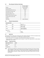
... (Gb/in2 avg) Spindle speed (RPM) (± 0.2%) Maximum Internal transfer rate (Mb/s) I/O data-transfer rate (Gb/s max) Interleave Cache buffer 4K sector models Serial ATA (SATA) Perpendicular 1397k 315k 425 7200 1247 3.0 1:1 16 MB (16,384 KB) 3.6 Physical characteristics Drive specification Height (mm) (in) Width (mm) (in) Length (mm) (in) Weight...
... (Gb/in2 avg) Spindle speed (RPM) (± 0.2%) Maximum Internal transfer rate (Mb/s) I/O data-transfer rate (Gb/s max) Interleave Cache buffer 4K sector models Serial ATA (SATA) Perpendicular 1397k 315k 425 7200 1247 3.0 1:1 16 MB (16,384 KB) 3.6 Physical characteristics Drive specification Height (mm) (in) Width (mm) (in) Length (mm) (in) Weight...
Momentus Thin (.2-4K) SATA Product Manual
Page 14
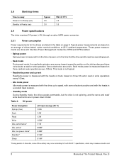
... to ready Power-on to Ready (sec) Standby to Ready (sec) Typical 3.5 3.0 Max @ 25°C 4.0 3.0 3.9 Power specifications The drive receives DC power (+5V) through a native SATA power connector. 3.9.1 Power consumption Power requirements for the drives are in the table on page 8. Seek mode power is measured based on three random seek...
... to ready Power-on to Ready (sec) Standby to Ready (sec) Typical 3.5 3.0 Max @ 25°C 4.0 3.0 3.9 Power specifications The drive receives DC power (+5V) through a native SATA power connector. 3.9.1 Power consumption Power requirements for the drives are in the table on page 8. Seek mode power is measured based on three random seek...
Momentus Thin (.2-4K) SATA Product Manual
Page 16
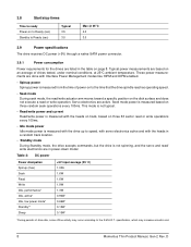
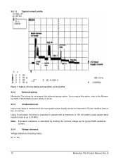
... power, the drive is expected to operate with a maximum of 100 mV peak-to-peak square-wave injected noise at up to the Momentus 5400.3 SATA Blade Server family of drives. 3.9.3 Conducted noise Input noise ripple is calculated by dividing the nominal voltage by the typical RMS read/write current. 3.9.4 Voltage...
... power, the drive is expected to operate with a maximum of 100 mV peak-to-peak square-wave injected noise at up to the Momentus 5400.3 SATA Blade Server family of drives. 3.9.3 Conducted noise Input noise ripple is calculated by dividing the nominal voltage by the typical RMS read/write current. 3.9.4 Voltage...

Momentus Thin (.2-4K) SATA Product Manual
Page 24
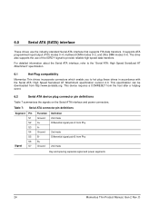
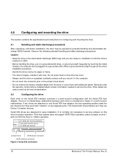
... surface until you mount it with the Serial ATA host adapter. Some factory-installed labels contain information needed to 1.5 Gbits per second Jumper block SATA power connector SATA interface connector Figure 2. If two drives are attached on one Serial ATA host adapter, the host operating system views the two devices as if... limit the drive to 1.5Gb/s operation. 3.0 Gbits per second operation Limit data transfer rate to service the drive. If the host system does not support SATA 3Gb/s operation, place a jumper on two separate ports.
... surface until you mount it with the Serial ATA host adapter. Some factory-installed labels contain information needed to 1.5 Gbits per second Jumper block SATA power connector SATA interface connector Figure 2. If two drives are attached on one Serial ATA host adapter, the host operating system views the two devices as if... limit the drive to 1.5Gb/s operation. 3.0 Gbits per second operation Limit data transfer rate to service the drive. If the host system does not support SATA 3Gb/s operation, place a jumper on two separate ports.

Momentus Thin (.2-4K) SATA Product Manual
Page 25
... the direct connection to ensure correct orientation. 4.4 Drive mounting You can be 30 to the drive or host. SATA interface connector Power connector SATA interface cable Power cable Figure 3. Attaching SATA cabling Each connector is keyed to be hot pluggable and blind mateable. See Figure 4 for connector pin definitions. ...Operating with no hard errors 10 mm probe: 1.02kgf or 5 mm probe: 0.92kgf 20 mm probe: 2kgf at any point of the SATA signal cable can mount the drive using four screws in the side-mounting holes or four screws in two differential pairs, plus three ground ...
... the direct connection to ensure correct orientation. 4.4 Drive mounting You can be 30 to the drive or host. SATA interface connector Power connector SATA interface cable Power cable Figure 3. Attaching SATA cabling Each connector is keyed to be hot pluggable and blind mateable. See Figure 4 for connector pin definitions. ...Operating with no hard errors 10 mm probe: 1.02kgf or 5 mm probe: 0.92kgf 20 mm probe: 2kgf at any point of the SATA signal cable can mount the drive using four screws in the side-mounting holes or four screws in two differential pairs, plus three ground ...
Momentus Thin (.2-4K) SATA Product Manual
Page 30
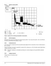
... mate Differential signal pair B from Phy 2nd mate Key and spacing separate signal and power segments 24 Momentus Thin Product Manual, Gen-2 Rev. 6.0 Serial ATA (SATA) interface These drives use of the IORDY signal to hot plug these drives in accordance with the Serial ATA: High Speed Serialized AT Attachment specification...
... mate Differential signal pair B from Phy 2nd mate Key and spacing separate signal and power segments 24 Momentus Thin Product Manual, Gen-2 Rev. 6.0 Serial ATA (SATA) interface These drives use of the IORDY signal to hot plug these drives in accordance with the Serial ATA: High Speed Serialized AT Attachment specification...
Momentus Thin (.2-4K) SATA Product Manual
Page 43
D 37 implementation 26 Safety certification 15 SATA 7, 24 screws 13, 19 sector 6 Sectors per track 6 Security Disable Password 27 Security Erase Prepare 27 Security Erase Unit 27 Security Freeze Lock 27 Security ...Set Password 27 Security Unlock 27 Seek 26 seek mode 8 Seek time 7 seek time 4 Seeking 8 Self refresh, low power 11 Serial ATA 7 Serial ATA (SATA) interface 24 serial ATA ports 3 servo electronics 8 Set Features 26 Set Max Address 26 Set Multiple Mode 26 Shock 13 Shock, nonoperating 5 Shock, operating 5 single...
D 37 implementation 26 Safety certification 15 SATA 7, 24 screws 13, 19 sector 6 Sectors per track 6 Security Disable Password 27 Security Erase Prepare 27 Security Erase Unit 27 Security Freeze Lock 27 Security ...Set Password 27 Security Unlock 27 Seek 26 seek mode 8 Seek time 7 seek time 4 Seeking 8 Self refresh, low power 11 Serial ATA 7 Serial ATA (SATA) interface 24 serial ATA ports 3 servo electronics 8 Set Features 26 Set Max Address 26 Set Multiple Mode 26 Shock 13 Shock, nonoperating 5 Shock, operating 5 single...
Momentus Thin SATA Product Manual
Page 3
Contents 1.0 Seagate Technology support services 1 2.0 Introduction 2 2.1 About the Serial ATA interface 3 3.0 Drive specifications 4 3.1 Specification summary table 4 3.2 Formatted capacity 6 3.2.1 LBA mode 6 3.3 Default logical geometry 6 3.4 ... 18 4.1 Handling and static-discharge precautions 18 4.2 Configuring the drive 18 4.3 Serial ATA cables and connectors 19 4.4 Drive mounting 19 5.0 Serial ATA (SATA) interface 21 5.1 Hot-Plug compatibility 21 5.2 Serial ATA device plug connector pin definitions 21 5.3 Supported ATA commands 23 5.3.1 Identify Device command 25 5.3.2 ...
Contents 1.0 Seagate Technology support services 1 2.0 Introduction 2 2.1 About the Serial ATA interface 3 3.0 Drive specifications 4 3.1 Specification summary table 4 3.2 Formatted capacity 6 3.2.1 LBA mode 6 3.3 Default logical geometry 6 3.4 ... 18 4.1 Handling and static-discharge precautions 18 4.2 Configuring the drive 18 4.3 Serial ATA cables and connectors 19 4.4 Drive mounting 19 5.0 Serial ATA (SATA) interface 21 5.1 Hot-Plug compatibility 21 5.2 Serial ATA device plug connector pin definitions 21 5.3 Supported ATA commands 23 5.3.1 Identify Device command 25 5.3.2 ...
Momentus Thin SATA Product Manual
Page 5
List of Figures Figure 1. B iii Figure 4. Figure 3. top, side and end view 20 Momentus Thin Product Manual, Rev. Figure 2. Typical +5V only startup and operation current profile 10 Serial ATA connectors 18 Attaching SATA cabling 19 Mounting dimensions (for standard models) -
List of Figures Figure 1. B iii Figure 4. Figure 3. top, side and end view 20 Momentus Thin Product Manual, Rev. Figure 2. Typical +5V only startup and operation current profile 10 Serial ATA connectors 18 Attaching SATA cabling 19 Mounting dimensions (for standard models) -
Momentus Thin SATA Product Manual
Page 10
...) 315k 425 Spindle speed (RPM) 5400 Average latency (ms) 5.6 Internal transfer rate (Mb/s max) 1044 I/O data transfer rate (Gb/s max) 3.0 ATA data-transfer modes supported SATA 1.0, Serial ATA Revision 2.6 PIO modes 0-4 Multiword DMA modes 0-2 Ultra DMA modes 0-6 Height (max) 7.0 mm (0.276 in) Width (max) 70.10 mm (2.76 in) Length (max...
...) 315k 425 Spindle speed (RPM) 5400 Average latency (ms) 5.6 Internal transfer rate (Mb/s max) 1044 I/O data transfer rate (Gb/s max) 3.0 ATA data-transfer modes supported SATA 1.0, Serial ATA Revision 2.6 PIO modes 0-4 Multiword DMA modes 0-2 Ultra DMA modes 0-6 Height (max) 7.0 mm (0.276 in) Width (max) 70.10 mm (2.76 in) Length (max...

Momentus Thin SATA Product Manual
Page 13
... (Gb/in2 avg) Spindle speed (RPM) (± 0.2%) Maximum Internal transfer rate (Mb/s) I/O data-transfer rate (Gb/s max) Interleave Cache buffer 4K sector models Serial ATA (SATA) Perpendicular 1397k 315k 425 5400 1044 3.0 1:1 8MB (8,192 KB) 3.6 Physical characteristics Drive specification Height (mm) (in) Width (mm) (in) Length (mm) (in which these drives...
... (Gb/in2 avg) Spindle speed (RPM) (± 0.2%) Maximum Internal transfer rate (Mb/s) I/O data-transfer rate (Gb/s max) Interleave Cache buffer 4K sector models Serial ATA (SATA) Perpendicular 1397k 315k 425 5400 1044 3.0 1:1 8MB (8,192 KB) 3.6 Physical characteristics Drive specification Height (mm) (in) Width (mm) (in) Length (mm) (in which these drives...
Momentus Thin SATA Product Manual
Page 14
... measurements are active. specification, which may occur according to Ready (sec) Typical 3.5 3.0 Max @ 25°C 4.0 3.0 3.9 Power specifications The drive receives DC power (+5V) through a native SATA power connector. 3.9.1 Power consumption Power requirements for the drives are done with the heads in a random track location. • Standby mode During Standby mode, the...
... measurements are active. specification, which may occur according to Ready (sec) Typical 3.5 3.0 Max @ 25°C 4.0 3.0 3.9 Power specifications The drive receives DC power (+5V) through a native SATA power connector. 3.9.1 Power consumption Power requirements for the drives are done with the heads in a random track location. • Standby mode During Standby mode, the...
Momentus Thin SATA Product Manual
Page 16
Equivalent resistance is measured at up to the Momentus 5400.3 SATA Blade Server family of 100 mV peak-to-peak square-wave injected noise at the host system power supply across an equivalent 15-ohm resistive ...
Equivalent resistance is measured at up to the Momentus 5400.3 SATA Blade Server family of 100 mV peak-to-peak square-wave injected noise at the host system power supply across an equivalent 15-ohm resistive ...
Momentus Thin SATA Product Manual
Page 24
...the specifications and instructions for easy installation. Some factory-installed labels contain information needed to 1.5 Gbits per second Jumper block SATA power connector SATA interface connector Figure 2. Serial ATA connectors 18 Momentus Thin Product Manual, Rev. This means both drives behave as if ...Do not remove the factory-installed labels from the drive or cover them with additional labels. If the host system does not support SATA 3Gb/s operation, place a jumper on a padded, antistatic surface until you mount it with the Serial ATA host adapter. Serial ATA...
...the specifications and instructions for easy installation. Some factory-installed labels contain information needed to 1.5 Gbits per second Jumper block SATA power connector SATA interface connector Figure 2. Serial ATA connectors 18 Momentus Thin Product Manual, Rev. This means both drives behave as if ...Do not remove the factory-installed labels from the drive or cover them with additional labels. If the host system does not support SATA 3Gb/s operation, place a jumper on a padded, antistatic surface until you mount it with the Serial ATA host adapter. Serial ATA...

Momentus Thin SATA Product Manual
Page 25
The cable size may be 30 to the drive or host. SATA interface connector Power connector SATA interface cable Power cable Figure 3. 4.3 Serial ATA cables and connectors The Serial ATA interface cable consists of four conductors in -lb (0.4519 N-m). • Four (4)... drive: • Allow a minimum clearance of 0.030 inches (0.76 mm) around the entire perimeter of the SATA signal cable can connect the drive as illustrated in the bottom-mounting holes. Attaching SATA cabling Each connector is keyed to the following specifications for cooling. • Use only M3 UNC mounting screws...
The cable size may be 30 to the drive or host. SATA interface connector Power connector SATA interface cable Power cable Figure 3. 4.3 Serial ATA cables and connectors The Serial ATA interface cable consists of four conductors in -lb (0.4519 N-m). • Four (4)... drive: • Allow a minimum clearance of 0.030 inches (0.76 mm) around the entire perimeter of the SATA signal cable can connect the drive as illustrated in the bottom-mounting holes. Attaching SATA cabling Each connector is keyed to the following specifications for cooling. • Use only M3 UNC mounting screws...

Momentus Thin SATA Product Manual
Page 27
5.0 Serial ATA (SATA) interface These drives use of the IORDY signal to hot plug these drives in accordance with the Serial ATA: High Speed Serialized AT Attachment specification ...
5.0 Serial ATA (SATA) interface These drives use of the IORDY signal to hot plug these drives in accordance with the Serial ATA: High Speed Serialized AT Attachment specification ...
Momentus Thin SATA Product Manual
Page 39
implementation 23 Safety certification 15 SATA 7, 21 screws 13, 19 sector 6 Sectors per track 6 Security Disable Password 24 Security Erase Prepare 24 Security Erase Unit 24 Security Freeze Lock 24 Security ...Set Password 24 Security Unlock 24 Seek 23 seek mode 8 Seek time 7 seek time 4 Seeking 8 Self refresh, low power 11 Serial ATA 7 Serial ATA (SATA) interface 21 serial ATA ports 3 servo electronics 8 Set Features 23 Set Max Address 23 Set Multiple Mode 23 Shock 13 Shock, nonoperating 5 Shock, operating 5 single...
implementation 23 Safety certification 15 SATA 7, 21 screws 13, 19 sector 6 Sectors per track 6 Security Disable Password 24 Security Erase Prepare 24 Security Erase Unit 24 Security Freeze Lock 24 Security ...Set Password 24 Security Unlock 24 Seek 23 seek mode 8 Seek time 7 seek time 4 Seeking 8 Self refresh, low power 11 Serial ATA 7 Serial ATA (SATA) interface 21 serial ATA ports 3 servo electronics 8 Set Features 23 Set Max Address 23 Set Multiple Mode 23 Shock 13 Shock, nonoperating 5 Shock, operating 5 single...

