Product Manual
Page 5
B 2.0 Configuring and mounting the drive 17 2.1 Handling and static-discharge precautions 17 2.2 Jumper settings 18 2.2.1 Master/slave configuration 18 2.2.2 Cable-select option 19 2.2.3 Alternate capacity jumper 19 2.2.4 Ultra ATA/100 cable 19 2.1 Drive mounting 20 3.0 ATA interface 21 3.1 ATA interface signals and connector pins 21 3.1.1 Supported ATA commands 23 3.1.2 Identify Drive command 24 3.1.3 Set Features command 29 3.1.4 S.M.A.R.T. commands 30 iv U Series 5 Family Product Manual, Rev.
B 2.0 Configuring and mounting the drive 17 2.1 Handling and static-discharge precautions 17 2.2 Jumper settings 18 2.2.1 Master/slave configuration 18 2.2.2 Cable-select option 19 2.2.3 Alternate capacity jumper 19 2.2.4 Ultra ATA/100 cable 19 2.1 Drive mounting 20 3.0 ATA interface 21 3.1 ATA interface signals and connector pins 21 3.1.1 Supported ATA commands 23 3.1.2 Identify Drive command 24 3.1.3 Set Features command 29 3.1.4 S.M.A.R.T. commands 30 iv U Series 5 Family Product Manual, Rev.
Product Manual
Page 8
U Series 5 Family Product Manual, Rev. B 1 Introduction This manual describes the functional, mechanical and interface specifications for excellent desktop performance • 350 Gs nonoperating shock • Giant magnetoresistive (GMR) recording heads and EPRML technol- It also includes installation instructions and jumper settings. • SeaTools diagnostic software performs a drive self-test that use cable select (CSEL) • The innovative, shock-absorbing SeaShield® cover protects the drive against electrostatic discharge (ESD) and other handling...
U Series 5 Family Product Manual, Rev. B 1 Introduction This manual describes the functional, mechanical and interface specifications for excellent desktop performance • 350 Gs nonoperating shock • Giant magnetoresistive (GMR) recording heads and EPRML technol- It also includes installation instructions and jumper settings. • SeaTools diagnostic software performs a drive self-test that use cable select (CSEL) • The innovative, shock-absorbing SeaShield® cover protects the drive against electrostatic discharge (ESD) and other handling...
Product Manual
Page 9
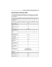
... 376 max) I/O data-transfer rate (Mbytes/sec 100 max) ATA data-transfer modes supported PIO modes 0-4 Multiword DMA modes 0-2 Ultra DMA modes 0-5 Cache buffer (Mbytes) 1 Height (mm max) 26.1 Width (mm max) 101.85 Length (mm max) 147.0 B Specification summary table The specifications listed in this manual. 2 U Series 5 Family Product Manual, Rev. For details on specification measurement or definition, see the appropriate section of this table are for quick reference. Drive Specification ST340823A ST330621A ST320413A ST315311A ST310211A Formatted...
... 376 max) I/O data-transfer rate (Mbytes/sec 100 max) ATA data-transfer modes supported PIO modes 0-4 Multiword DMA modes 0-2 Ultra DMA modes 0-5 Cache buffer (Mbytes) 1 Height (mm max) 26.1 Width (mm max) 101.85 Length (mm max) 147.0 B Specification summary table The specifications listed in this manual. 2 U Series 5 Family Product Manual, Rev. For details on specification measurement or definition, see the appropriate section of this table are for quick reference. Drive Specification ST340823A ST330621A ST320413A ST315311A ST310211A Formatted...
Product Manual
Page 12
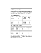
... 1.1.1 Default logical geometry CHS Mode ST340823A ST330621A ST320413A ST315311A ST310211A Cylinders 16,383 16,383 16,383 16,383 16,383 Read/Write heads 16 16 16 16 16 Sectors per track 63 63 63 63 63 LBA Mode When addressing either drive in LBA mode, all specifications are consecutively numbered from 0 to n-1, where n is the number of guaranteed sectors as defined above. B 5 1.0 Drive specifications Unless otherwise noted, all blocks (sectors...
... 1.1.1 Default logical geometry CHS Mode ST340823A ST330621A ST320413A ST315311A ST310211A Cylinders 16,383 16,383 16,383 16,383 16,383 Read/Write heads 16 16 16 16 16 Sectors per track 63 63 63 63 63 LBA Mode When addressing either drive in LBA mode, all specifications are consecutively numbered from 0 to n-1, where n is the number of guaranteed sectors as defined above. B 5 1.0 Drive specifications Unless otherwise noted, all blocks (sectors...
Product Manual
Page 13
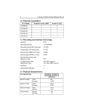
... organization Drive Model Read/Write heads (GMR) ST340823A 4 ST330621A 3 ST320413A 2 ST315311A 2 ST310211A 1 Number of discs 2 2 1 1 1 1.3 Recording and interface technology Interface ATA Recording method 16/17 EPRML Recording density BPI (bits/inch) 477,800 Track density TPI (tracks/inch) 31,100 Areal density (Mbits/inch2 max) 14,860 Spindle speed (RPM) (± 0.2%) 5,400 Internal data-transfer rate (Mbits/sec max) 376 I/O data-transfer rate (Mbytes/sec max) 16.6 (PIO mode 4) 100 (Ultra DMA mode 5) Interleave 1:1 Cache...
... organization Drive Model Read/Write heads (GMR) ST340823A 4 ST330621A 3 ST320413A 2 ST315311A 2 ST310211A 1 Number of discs 2 2 1 1 1 1.3 Recording and interface technology Interface ATA Recording method 16/17 EPRML Recording density BPI (bits/inch) 477,800 Track density TPI (tracks/inch) 31,100 Areal density (Mbits/inch2 max) 14,860 Spindle speed (RPM) (± 0.2%) 5,400 Internal data-transfer rate (Mbits/sec max) 376 I/O data-transfer rate (Mbytes/sec max) 16.6 (PIO mode 4) 100 (Ultra DMA mode 5) Interleave 1:1 Cache...

Product Manual
Page 14
... with nominal power at least 5,000 measurements of mode (such as track-to-track and average) are formatted, benchmark tests that include command overhead or measure logical seeks may produce results that vary from the first data cylinder to the maximum data cylinder and back to the first data cylinder. Typical seek times (msec) Read Write Track-to meet the seek times represented in both directions. • Average seek time is...
... with nominal power at least 5,000 measurements of mode (such as track-to-track and average) are formatted, benchmark tests that include command overhead or measure logical seeks may produce results that vary from the first data cylinder to the maximum data cylinder and back to the first data cylinder. Typical seek times (msec) Read Write Track-to meet the seek times represented in both directions. • Average seek time is...

Product Manual
Page 15
... a specific position on the disc surface and does not execute a read or write operation. B 1.7.1 Power consumption Power requirements for each 10 reads) and 20 percent drive inactive. • Idle mode power Idle mode power is measured from the time of drives tested, under nominal conditions, using only random seeks with the heads in the table on to speed, with servo electronics active and with read /write electronics are active. 8 U Series 5 Family Product Manual, Rev. Typical power measurements...
... a specific position on the disc surface and does not execute a read or write operation. B 1.7.1 Power consumption Power requirements for each 10 reads) and 20 percent drive inactive. • Idle mode power Idle mode power is measured from the time of drives tested, under nominal conditions, using only random seeks with the heads in the table on to speed, with servo electronics active and with read /write electronics are active. 8 U Series 5 Family Product Manual, Rev. Typical power measurements...
Product Manual
Page 17
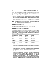
... power-management modes: Power Modes Heads Spindle Buffer Active Tracking Rotating Enabled Idle Tracking Rotating Enabled Standby Parked Stopped Enabled Sleep Parked Stopped Disabled • Active mode The drive is in Active mode during the read/write and seek operations. • Idle mode The buffer remains enabled, and the drive accepts all commands and returns to Active mode any time disc access is calculated by dividing the nominal voltage by the typical RMS read/write current. 1.7.3 Voltage tolerance Voltage...
... power-management modes: Power Modes Heads Spindle Buffer Active Tracking Rotating Enabled Idle Tracking Rotating Enabled Standby Parked Stopped Enabled Sleep Parked Stopped Disabled • Active mode The drive is in Active mode during the read/write and seek operations. • Idle mode The buffer remains enabled, and the drive accepts all commands and returns to Active mode any time disc access is calculated by dividing the nominal voltage by the typical RMS read/write current. 1.7.3 Voltage tolerance Voltage...

Product Manual
Page 18
... drive case temperature should not exceed 65°C (149°F) within the operating ambient conditions. U Series 5 Family Product Manual, Rev. After receiving a reset, the drive exits Sleep mode and enters Standby mode with all commands and returns to 158°F) 1.8.2 Temperature gradient Operating/Nonoperating 20°C per hour (36°F per hour) max, without condensation 1.8.3 Humidity If the standby timer reaches zero before any time disc access is disabled, the heads...
... drive case temperature should not exceed 65°C (149°F) within the operating ambient conditions. U Series 5 Family Product Manual, Rev. After receiving a reset, the drive exits Sleep mode and enters Standby mode with all commands and returns to 158°F) 1.8.2 Temperature gradient Operating/Nonoperating 20°C per hour (36°F per hour) max, without condensation 1.8.3 Humidity If the standby timer reaches zero before any time disc access is disabled, the heads...
Product Manual
Page 22
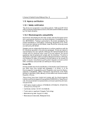
...-user system by EN 55024. U Series 5 Family Product Manual, Rev. B 15 1.12 Agency certification 1.12.1 Safety certification The drives are tested in accordance with UL 1950 and CSA C22.2 (950) and meet all systems will comply with the Electromagnetic Interference/Electromagnetic Susceptibility (EMI/EMS) for operation inside a properly designed enclosure, with paragraph 1 of Article 11 of the Electromagnetic Compatibility control...
...-user system by EN 55024. U Series 5 Family Product Manual, Rev. B 15 1.12 Agency certification 1.12.1 Safety certification The drives are tested in accordance with UL 1950 and CSA C22.2 (950) and meet all systems will comply with the Electromagnetic Interference/Electromagnetic Susceptibility (EMI/EMS) for operation inside a properly designed enclosure, with paragraph 1 of Article 11 of the Electromagnetic Compatibility control...
Product Manual
Page 23
... a residential installation. Refer to provide reasonable protection against such interference in enclosures as an external device). B Australian C-Tick (N176) If these models have the C-Tick marking, they comply with the Australia/ New Zealand Standard AS/NZS3548 1995 and meet the Electromagnetic Compatibility (EMC) Framework requirements of the Australian Communication Authority (ACA). 1.12.3 FCC verification These drives are on...
... a residential installation. Refer to provide reasonable protection against such interference in enclosures as an external device). B Australian C-Tick (N176) If these models have the C-Tick marking, they comply with the Australia/ New Zealand Standard AS/NZS3548 1995 and meet the Electromagnetic Compatibility (EMC) Framework requirements of the Australian Communication Authority (ACA). 1.12.3 FCC verification These drives are on...
Product Manual
Page 24
... against external shocks and stresses. B 17 2.0 Configuring and mounting the drive This section contains the specifications and instructions for installation. • The drive is extremely fragile-handle it protects the drive from electrostatic discharge (ESD) and minor impact damage. The design permits attaching cables, software loading and label/barcode scanning without removing the drive from the drive or cover them with care. Removing the...
... against external shocks and stresses. B 17 2.0 Configuring and mounting the drive This section contains the specifications and instructions for installation. • The drive is extremely fragile-handle it protects the drive from electrostatic discharge (ESD) and minor impact damage. The design permits attaching cables, software loading and label/barcode scanning without removing the drive from the drive or cover them with care. Removing the...
Product Manual
Page 25
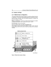
...used to configure the drive as master with non ATAcompatible slave Cable select Limit drive capacity 40 Gbytes = 32 GB Use the following settings to configure the drive for a master or single-drive operation with no jumpers installed. B 2.2 Jumper settings 2.2.1 Master/slave configuration The options jumper block shown in Figure 2 is slave Master with a non-ATA-compatible slave. Master or single drive. Set a jumper on pins 5 and 6 and a jumper on pins 7 and 8. Drive as a master or a slave. 18 U Series 5 Family Product Manual, Rev. It is configured at the factory...
...used to configure the drive as master with non ATAcompatible slave Cable select Limit drive capacity 40 Gbytes = 32 GB Use the following settings to configure the drive for a master or single-drive operation with no jumpers installed. B 2.2 Jumper settings 2.2.1 Master/slave configuration The options jumper block shown in Figure 2 is slave Master with a non-ATA-compatible slave. Master or single drive. Set a jumper on pins 5 and 6 and a jumper on pins 7 and 8. Drive as a master or a slave. 18 U Series 5 Family Product Manual, Rev. It is configured at the factory...
Product Manual
Page 26
... connector to the master drive, and the grey connector to improve signal integrity. To enable cable select, set a jumper on pins 5 and 6 as DiscWizard or Disk Manager. Master and slave drives are needed to support drives with capacities greater than either 4,092 cylinders or approximately 33.8 Gbytes (32 GB). To realize the full capacity of word 93 in ID words 60 and 61. This cable uses even-numbered conductors connected to the ground pins to the slave. Windows...
... connector to the master drive, and the grey connector to improve signal integrity. To enable cable select, set a jumper on pins 5 and 6 as DiscWizard or Disk Manager. Master and slave drives are needed to support drives with capacities greater than either 4,092 cylinders or approximately 33.8 Gbytes (32 GB). To realize the full capacity of word 93 in ID words 60 and 61. This cable uses even-numbered conductors connected to the ground pins to the slave. Windows...

Product Manual
Page 28
B 21 3.0 ATA interface These drives use the industry-standard ATA task file interface that the drive supports. multiword DMA modes 0-2, and Ultra DMA modes 0-5. The drive also supports the use a daisy-chain cable to connect two drives to as the Draft ATA-Rev 5 Standard. 3.1 ATA interface signals and connector pins Figure 4 on page 22 summarizes the signals on the ATA interface connector that supports 16-bit data transfers. For detailed information about the ATA interface, refer to the draft of AT Attachment...
B 21 3.0 ATA interface These drives use the industry-standard ATA task file interface that the drive supports. multiword DMA modes 0-2, and Ultra DMA modes 0-5. The drive also supports the use a daisy-chain cable to connect two drives to as the Draft ATA-Rev 5 Standard. 3.1 ATA interface signals and connector pins Figure 4 on page 22 summarizes the signals on the ATA interface connector that supports 16-bit data transfers. For detailed information about the ATA interface, refer to the draft of AT Attachment...
Product Manual
Page 30
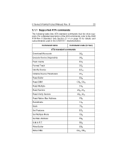
... Execute Device Diagnostics Flush Cache Format Track Identify Device Initialize Device Parameters Read Buffer Read DMA Read Multiple Read Sectors Read Verify Sectors Read Native Max Address Recalibrate Seek Set Features Set Multiple Mode Set Max Address S.M.A.R.T. Write Buffer Write DMA 92H 90H E7H 50H ECH 91H E4H C8H, C9H C4H 20H, 21H 40H, 41H F8H 10H 70H EFH C6H F9H B0H E8H CAH, CBH B 23 3.1.1 Supported ATA commands The following table lists ATA-standard commands that the drive supports. U Series 5 Family Product Manual...
... Execute Device Diagnostics Flush Cache Format Track Identify Device Initialize Device Parameters Read Buffer Read DMA Read Multiple Read Sectors Read Verify Sectors Read Native Max Address Recalibrate Seek Set Features Set Multiple Mode Set Max Address S.M.A.R.T. Write Buffer Write DMA 92H 90H E7H 50H ECH 91H E4H C8H, C9H C4H 20H, 21H 40H, 41H F8H 10H 70H EFH C6H F9H B0H E8H CAH, CBH B 23 3.1.1 Supported ATA commands The following table lists ATA-standard commands that the drive supports. U Series 5 Family Product Manual...
Product Manual
Page 31
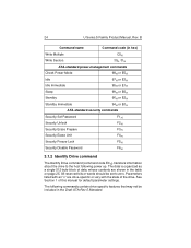
... Standby 96H or E2H Standby Immediate 94H or E0H ATA-standard security commands Security Set Password F1H Security Unlock F2H Security Erase Prepare F3H Security Erase Unit F4H Security Freeze Lock F5H Security Disable Password F6H 3.1.2 Identify Drive command The Identify Drive command (command code ECH) transfers information about the drive to zero. The data is organized as a single 512-byte block of data, whose contents are drive-specific or vary with the state of this manual for default parameter settings. The following power up.
... Standby 96H or E2H Standby Immediate 94H or E0H ATA-standard security commands Security Set Password F1H Security Unlock F2H Security Erase Prepare F3H Security Erase Unit F4H Security Freeze Lock F5H Security Disable Password F6H 3.1.2 Identify Drive command The Identify Drive command (command code ECH) transfers information about the drive to zero. The data is organized as a single 512-byte block of data, whose contents are drive-specific or vary with the state of this manual for default parameter settings. The following power up.

Product Manual
Page 33
... a Read Multiple or Write Multiple command xxxxH xxxxH xxxxH Total number of user-addressable LBA sectors available (see section 2.2.3 for related information) ST340823A = 78,165,360 ST330621A = 58,633,344 ST320413A = 39,102,336 ST315311A = 30,008,475 ST310211A = 20,005,650 Retired Multiword DMA active and modes supported (see note following this table) 0000H xx07H Advanced PIO modes supported (modes 3 and 4 supported) 0003H 26 U Series 5 Family Product Manual...
... a Read Multiple or Write Multiple command xxxxH xxxxH xxxxH Total number of user-addressable LBA sectors available (see section 2.2.3 for related information) ST340823A = 78,165,360 ST330621A = 58,633,344 ST320413A = 39,102,336 ST315311A = 30,008,475 ST310211A = 20,005,650 Retired Multiword DMA active and modes supported (see note following this table) 0000H xx07H Advanced PIO modes supported (modes 3 and 4 supported) 0003H 26 U Series 5 Family Product Manual...

Product Manual
Page 34
...) Minimum PIO cycle time with IORDY flow control (120 nsec) ATA-reserved Queue depth ATA-reserved Major version number Minor version number Command sets supported Command sets supported Command sets support extension Command sets enabled Command sets enabled Command sets enable extension Ultra DMA support and current mode (see note following this table) Security erase time Enhanced security erase time 27 Value 0078H 0078H 00F0H 0078H 0000H 0000H 0000H 003EH 0000H 346BH 4009H 4209H xxxxH xxxxH xxxxH xx3FH 0000H 0000H U Series 5 Family Product Manual, Rev.
...) Minimum PIO cycle time with IORDY flow control (120 nsec) ATA-reserved Queue depth ATA-reserved Major version number Minor version number Command sets supported Command sets supported Command sets support extension Command sets enabled Command sets enabled Command sets enable extension Ultra DMA support and current mode (see note following this table) Security erase time Enhanced security erase time 27 Value 0078H 0078H 00F0H 0078H 0000H 0000H 0000H 003EH 0000H 346BH 4009H 4209H xxxxH xxxxH xxxxH xx3FH 0000H 0000H U Series 5 Family Product Manual, Rev.
Product Manual
Page 35
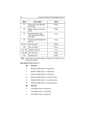
... mode 2 is currently active. B Word Description Value 91 Advanced Power Management value 0040H 92 Master Password Revision code FFFEH 93 Hardware Reset Value (see description following this table) xxxxH 94 Auto Acoustic Management Setting xxxxH 95-127 ATA-reserved 0000H 128 Security Status 0001H 129-159 Seagate-reserved xxxxH 160-254 ATA-reserved 0000H 255 Integrity word xxA5H Note. 28 U Series 5 Family Product Manual...
... mode 2 is currently active. B Word Description Value 91 Advanced Power Management value 0040H 92 Master Password Revision code FFFEH 93 Hardware Reset Value (see description following this table) xxxxH 94 Auto Acoustic Management Setting xxxxH 95-127 ATA-reserved 0000H 128 Security Status 0001H 129-159 Seagate-reserved xxxxH 160-254 ATA-reserved 0000H 255 Integrity word xxA5H Note. 28 U Series 5 Family Product Manual...


