Product Manual
Page 6
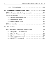
commands 29 B 1.12.3 FCC verification 14 2.0 Configuring and mounting the drive 15 2.1 Handling and static-discharge precautions 15 2.2 Jumper settings 16 2.2.1 Master/slave configuration 16 2.2.2 Cable-select option 17 2.2.3 Ultra ATA/100 cable 17 2.1 Drive mounting 18 3.0 ATA interface 19 3.1 ATA interface signals and connector pins 19 3.1.1 Supported ATA commands 21 3.1.2 Identify Drive command 22 3.1.3 Set Features command 27 3.1.4 S.M.A.R.T. vi ST310014ACE Product Manual, Rev.
commands 29 B 1.12.3 FCC verification 14 2.0 Configuring and mounting the drive 15 2.1 Handling and static-discharge precautions 15 2.2 Jumper settings 16 2.2.1 Master/slave configuration 16 2.2.2 Cable-select option 17 2.2.3 Ultra ATA/100 cable 17 2.1 Drive mounting 18 3.0 ATA interface 19 3.1 ATA interface signals and connector pins 19 3.1.1 Supported ATA commands 21 3.1.2 Identify Drive command 22 3.1.3 Set Features command 27 3.1.4 S.M.A.R.T. vi ST310014ACE Product Manual, Rev.

Product Manual
Page 7
Typical startup and operation current profile 7 Figure 2. Mounting dimensions-top, side and end view 18 Figure 4. ST310014ACE Product Manual, Rev. Master/slave jumper settings 16 Figure 3. I/O pins and supported ATA signals 20 B vii Figures Figure 1.
Typical startup and operation current profile 7 Figure 2. Mounting dimensions-top, side and end view 18 Figure 4. ST310014ACE Product Manual, Rev. Master/slave jumper settings 16 Figure 3. I/O pins and supported ATA signals 20 B vii Figures Figure 1.
Product Manual
Page 24
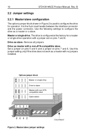
... a jumper set on pins 7 and 8. Drive as a master with a non-ATA-compatible slave. 16 ST310014ACE Product Manual, Rev. Master/slave jumper settings Circuit Board Use the following settings to configure the drive for a master or single-drive operation with non ATAcompatible slave Cable select 7531 8642 Figure 2. Remove all jumpers. Set a jumper on pins 5 and 6 and a jumper on pins 7 and 8. Use this jumper setting only...
... a jumper set on pins 7 and 8. Drive as a master with a non-ATA-compatible slave. 16 ST310014ACE Product Manual, Rev. Master/slave jumper settings Circuit Board Use the following settings to configure the drive for a master or single-drive operation with non ATAcompatible slave Cable select 7531 8642 Figure 2. Remove all jumpers. Set a jumper on pins 5 and 6 and a jumper on pins 7 and 8. Use this jumper setting only...
Product Manual
Page 25
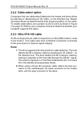
... the slave. signal. The host detects the 80-conductor cable by sensing a capacitor at the host side through the CBLID- ST310014ACE Product Manual, Rev. The drive detects the 80-conductor cable by sampling pin 34, CBLID-, on the interface bus. Refer to your computer manual to run ... bit (bit 13 of word 93 in Figure 2 on the cable. To enable cable select, set a jumper on pins 5 and 6 as shown in the Identify drive parameter block). 2. The drive supports both host and drive cable detection. When using a 40-pin 80-conductor cable, attach the blue connector to the motherboard...
... the slave. signal. The host detects the 80-conductor cable by sensing a capacitor at the host side through the CBLID- ST310014ACE Product Manual, Rev. The drive detects the 80-conductor cable by sampling pin 34, CBLID-, on the interface bus. Refer to your computer manual to run ... bit (bit 13 of word 93 in Figure 2 on the cable. To enable cable select, set a jumper on pins 5 and 6 as shown in the Identify drive parameter block). 2. The drive supports both host and drive cable detection. When using a 40-pin 80-conductor cable, attach the blue connector to the motherboard...

