
Product Manual
Page 5
... 1 Specification summary table 2 1.0 Drive specifications 4 1.1 Formatted capacity 4 1.1.1 Default logical geometry 4 1.2 Physical organization 4 1.3 Recording and interface technology 4 1.4 Physical characteristics 5 1.5 Start/stop times 5 1.6 Seek times 5 1.7 Power specifications 6 1.7.1 Power consumption 6 1.7.2 Conducted noise 8 1.7.3 Voltage tolerance 8 1.7.4 Power-management modes 8 1.8 Environmental tolerances 9 1.8.1 Ambient temperature 9 1.8.2 Temperature gradient 9 1.8.3 Humidity 10 1.8.4 Altitude 10 1.8.5 Shock 10 1.8.6 Vibration 10 1.9 Drive acoustics 11 1.10...
... 1 Specification summary table 2 1.0 Drive specifications 4 1.1 Formatted capacity 4 1.1.1 Default logical geometry 4 1.2 Physical organization 4 1.3 Recording and interface technology 4 1.4 Physical characteristics 5 1.5 Start/stop times 5 1.6 Seek times 5 1.7 Power specifications 6 1.7.1 Power consumption 6 1.7.2 Conducted noise 8 1.7.3 Voltage tolerance 8 1.7.4 Power-management modes 8 1.8 Environmental tolerances 9 1.8.1 Ambient temperature 9 1.8.2 Temperature gradient 9 1.8.3 Humidity 10 1.8.4 Altitude 10 1.8.5 Shock 10 1.8.6 Vibration 10 1.9 Drive acoustics 11 1.10...
Product Manual
Page 6
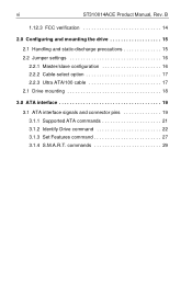
B 1.12.3 FCC verification 14 2.0 Configuring and mounting the drive 15 2.1 Handling and static-discharge precautions 15 2.2 Jumper settings 16 2.2.1 Master/slave configuration 16 2.2.2 Cable-select option 17 2.2.3 Ultra ATA/100 cable 17 2.1 Drive mounting 18 3.0 ATA interface 19 3.1 ATA interface signals and connector pins 19 3.1.1 Supported ATA commands 21 3.1.2 Identify Drive command 22 3.1.3 Set Features command 27 3.1.4 S.M.A.R.T. commands 29 vi ST310014ACE Product Manual, Rev.
B 1.12.3 FCC verification 14 2.0 Configuring and mounting the drive 15 2.1 Handling and static-discharge precautions 15 2.2 Jumper settings 16 2.2.1 Master/slave configuration 16 2.2.2 Cable-select option 17 2.2.3 Ultra ATA/100 cable 17 2.1 Drive mounting 18 3.0 ATA interface 19 3.1 ATA interface signals and connector pins 19 3.1.1 Supported ATA commands 21 3.1.2 Identify Drive command 22 3.1.3 Set Features command 27 3.1.4 S.M.A.R.T. commands 29 vi ST310014ACE Product Manual, Rev.
Product Manual
Page 9
... technol- ST310014ACE Product Manual, Rev. drive monitoring and reporting • Support for the ST310014ACE. Execute Off-line Immediate • Support for Read Multiple and Write Multiple commands • Support for autodetection of -the-art cache and on-the-fly error-correction algorithms • Full-track multiple-sector transfer capability without local processor intervention • Quiet operation • 350 Gs nonoperating shock • SeaTools diagnostic software performs a drive self-test that use cable select (CSEL...
... technol- ST310014ACE Product Manual, Rev. drive monitoring and reporting • Support for the ST310014ACE. Execute Off-line Immediate • Support for Read Multiple and Write Multiple commands • Support for autodetection of -the-art cache and on-the-fly error-correction algorithms • Full-track multiple-sector transfer capability without local processor intervention • Quiet operation • 350 Gs nonoperating shock • SeaTools diagnostic software performs a drive self-test that use cable select (CSEL...
Product Manual
Page 10
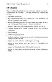
.../inch) Areal density (Mbits/inch2 max) Spindle speed (RPM) Internal data-transfer rate (Mbits/sec max) I/O data-transfer rate (Mbytes/sec max) ATA data-transfer modes supported Cache buffer (Mbytes) Height (mm max) Width (mm max) Length (mm max) Weight (typical) Average seek time (msec typical) Track-to-track seek time (msec typical) Read/write seek time (msec typical) Full-stroke seek time (msec typical) Power-on specification measurement or definition, see the appropriate section of this table are for quick reference. 2 ST310014ACE Product Manual, Rev.
.../inch) Areal density (Mbits/inch2 max) Spindle speed (RPM) Internal data-transfer rate (Mbits/sec max) I/O data-transfer rate (Mbytes/sec max) ATA data-transfer modes supported Cache buffer (Mbytes) Height (mm max) Width (mm max) Length (mm max) Weight (typical) Average seek time (msec typical) Track-to-track seek time (msec typical) Read/write seek time (msec typical) Full-stroke seek time (msec typical) Power-on specification measurement or definition, see the appropriate section of this table are for quick reference. 2 ST310014ACE Product Manual, Rev.

Product Manual
Page 11
ST310014ACE Product Manual, Rev. and nonop.) Relative humidity gradient Wet bulb temperature (°C max) Altitude, operating Altitude, nonoperating (meters relative to mean sea level) Shock, operating (Gs max at 2 msec) Shock, nonoperating (Gs max at 1 and 2 msec) Vibration, operating Vibration, nonoperating Drive acoustics Sound power in bels Nonrecoverable read errors Mean time between failures (power-on hours) Contact start-stop cycles (25°C, 40% relative humidity) SeaShield ST310014ACE 6.5 sec...
ST310014ACE Product Manual, Rev. and nonop.) Relative humidity gradient Wet bulb temperature (°C max) Altitude, operating Altitude, nonoperating (meters relative to mean sea level) Shock, operating (Gs max at 2 msec) Shock, nonoperating (Gs max at 1 and 2 msec) Vibration, operating Vibration, nonoperating Drive acoustics Sound power in bels Nonrecoverable read errors Mean time between failures (power-on hours) Contact start-stop cycles (25°C, 40% relative humidity) SeaShield ST310014ACE 6.5 sec...
Product Manual
Page 12
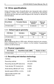
... number of guaranteed sectors as defined above. 1.2 Physical organization Drive Model Read/Write heads (GMR) ST310014ACE 1 Number of discs 1 1.3 Recording and interface technology Interface ATA Recording method 96/102 GPRML Recording density BPI (bits/inch) 376,200 Track density TPI (tracks/inch) Areal density (Mbits/inch2 max) 58,000 21,800 Spindle speed (RPM) (± 0.2%) 5,400 Internal data-transfer rate (Mbits/sec max) 366 4 ST310014ACE Product Manual, Rev. B 1.0 Drive specifications Unless otherwise noted, all blocks (sectors...
... number of guaranteed sectors as defined above. 1.2 Physical organization Drive Model Read/Write heads (GMR) ST310014ACE 1 Number of discs 1 1.3 Recording and interface technology Interface ATA Recording method 96/102 GPRML Recording density BPI (bits/inch) 376,200 Track density TPI (tracks/inch) Areal density (Mbits/inch2 max) 58,000 21,800 Spindle speed (RPM) (± 0.2%) 5,400 Internal data-transfer rate (Mbits/sec max) 366 4 ST310014ACE Product Manual, Rev. B 1.0 Drive specifications Unless otherwise noted, all blocks (sectors...

Product Manual
Page 13
... the first data cylinder. Seek time specifications are defined as follows: • Track-to ready (sec max) 12.7 1.2 (read) 2.0 (write) 18.0 (read) 24.9 (write) 36.8 (read); 42.0(write) 7 sec Seek measurements are measured using drive diagnostics. B 5 I/O data-transfer rate (Mbytes/sec max) Interleave Cache buffer (Mbytes) 16.6 (PIO mode 4) 100 (Ultra DMA mode 5) 1:1 2 1.4 Physical characteristics Drive Specification Maximum height mm (inches) Maximum width mm (inches) Maximum length mm (inches) Typical weight grams (pounds) ST310014ACE 19.99...
... the first data cylinder. Seek time specifications are defined as follows: • Track-to ready (sec max) 12.7 1.2 (read) 2.0 (write) 18.0 (read) 24.9 (write) 36.8 (read); 42.0(write) 7 sec Seek measurements are measured using drive diagnostics. B 5 I/O data-transfer rate (Mbytes/sec max) Interleave Cache buffer (Mbytes) 16.6 (PIO mode 4) 100 (Ultra DMA mode 5) 1:1 2 1.4 Physical characteristics Drive Specification Maximum height mm (inches) Maximum width mm (inches) Maximum length mm (inches) Typical weight grams (pounds) ST310014ACE 19.99...

Product Manual
Page 14
... that the drive spindle reaches operating speed. • Seek Mode The read or written during this manual consistently. However, due to the time that vary from these specifications. 1.7 Power specifications The drive receives DC power (+5V or +12V) through a four-pin standard drive power connector. 1.7.1 Power consumption Power requirements for the drives are based on an average of drives tested, under nominal conditions, using 5.0V input voltage at 25°C ambient temperature. • Spinup power Spinup power is...
... that the drive spindle reaches operating speed. • Seek Mode The read or written during this manual consistently. However, due to the time that vary from these specifications. 1.7 Power specifications The drive receives DC power (+5V or +12V) through a four-pin standard drive power connector. 1.7.1 Power consumption Power requirements for the drives are based on an average of drives tested, under nominal conditions, using 5.0V input voltage at 25°C ambient temperature. • Spinup power Spinup power is...
Product Manual
Page 16
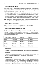
... can also enter Standby mode automatically after the drive has been inactive for a specifiable length of 100 mV peak-to-peak square-wave injected noise at up to 10 MHz. • Using 5-volt power, the drive is expected to operate with a maximum of time. 8 ST310014ACE Product Manual, Rev. If the host has set the standby timer, the drive can control power management through the system...
... can also enter Standby mode automatically after the drive has been inactive for a specifiable length of 100 mV peak-to-peak square-wave injected noise at up to 10 MHz. • Using 5-volt power, the drive is expected to operate with a maximum of time. 8 ST310014ACE Product Manual, Rev. If the host has set the standby timer, the drive can control power management through the system...

Product Manual
Page 17
... Standby mode. In both Idle and Standby mode, the drive accepts all commands and returns to Active mode when disc access is necessary. 1.8 Environmental tolerances 1.8.1 Ambient temperature Ambient temperature is necessary. • Sleep mode The drive enters Sleep mode after it receives a Hard Reset or Soft Reset from its specified delay times to 158°F) 1.8.2 Temperature gradient Operating/Nonoperating 20°C per hour (36°F per hour) max, without condensation ST310014ACE Product Manual...
... Standby mode. In both Idle and Standby mode, the drive accepts all commands and returns to Active mode when disc access is necessary. 1.8 Environmental tolerances 1.8.1 Ambient temperature Ambient temperature is necessary. • Sleep mode The drive enters Sleep mode after it receives a Hard Reset or Soft Reset from its specified delay times to 158°F) 1.8.2 Temperature gradient Operating/Nonoperating 20°C per hour (36°F per hour) max, without condensation ST310014ACE Product Manual...
Product Manual
Page 21
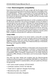
... arrow inside a properly designed enclosure, with properly shielded I /O ports. Drives are defined by EN 55022, Class B and the immunity levels are tested in the Electromagnetic Compatibility Directive (89/336/EEC). ST310014ACE Product Manual, Rev. B 13 1.12.2 Electromagnetic compatibility Hard drives that all unused I /O cable (if necessary) and terminators on all systems will comply with the directives when used in the previous paragraph...
... arrow inside a properly designed enclosure, with properly shielded I /O ports. Drives are defined by EN 55022, Class B and the immunity levels are tested in the Electromagnetic Compatibility Directive (89/336/EEC). ST310014ACE Product Manual, Rev. B 13 1.12.2 Electromagnetic compatibility Hard drives that all unused I /O cable (if necessary) and terminators on all systems will comply with the directives when used in the previous paragraph...

Product Manual
Page 22
14 ST310014ACE Product Manual, Rev. Seagate Technology, LLC has tested this device in enclosures as an external device). This equipment generates and uses radio frequency energy and if not installed and used in interference to radio and television reception. However, there...against such interference in a particular installation. As a subassembly, no guarantee that the total assembly (enclosure, disc drive, motherboard, power supply, etc.) does comply with the Australia/New Zealand Standard AS/NZS3548 1995 and meets the Electromagnetic Compatibility (EMC) Framework requirements of the...
14 ST310014ACE Product Manual, Rev. Seagate Technology, LLC has tested this device in enclosures as an external device). This equipment generates and uses radio frequency energy and if not installed and used in interference to radio and television reception. However, there...against such interference in a particular installation. As a subassembly, no guarantee that the total assembly (enclosure, disc drive, motherboard, power supply, etc.) does comply with the Australia/New Zealand Standard AS/NZS3548 1995 and meets the Electromagnetic Compatibility (EMC) Framework requirements of the...

Product Manual
Page 23
... a drive's exposure to service the drive. Some factoryinstalled labels contain information needed to ESD and also protects against external shocks and stresses. Observe the following standard handling and static-discharge precautions: Caution: • The SeaShell™ replaces electrostatic discharge (ESD) bags. ST310014ACE Product Manual, Rev. B 15 2.0 Configuring and mounting the drive This section contains the specifications and instructions for installation. • Before handling the drive, put...
... a drive's exposure to service the drive. Some factoryinstalled labels contain information needed to ESD and also protects against external shocks and stresses. Observe the following standard handling and static-discharge precautions: Caution: • The SeaShell™ replaces electrostatic discharge (ESD) bags. ST310014ACE Product Manual, Rev. B 15 2.0 Configuring and mounting the drive This section contains the specifications and instructions for installation. • Before handling the drive, put...
Product Manual
Page 24
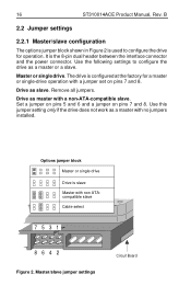
... jumper set on pins 7 and 8. The drive is used to configure the drive as a master with a non-ATA-compatible slave. Remove all jumpers. Master or single drive. Use the following settings to configure the drive for a master or single-drive operation with non ATAcompatible slave Cable select 7531 8642 Figure 2. Set a jumper on pins 5 and 6 and a jumper on pins 7 and 8. Drive as master with no jumpers installed. Use this jumper setting only if the drive does not work as a master or a slave. Drive as slave. Master/slave jumper settings Circuit Board 16 ST310014ACE...
... jumper set on pins 7 and 8. The drive is used to configure the drive as a master with a non-ATA-compatible slave. Remove all jumpers. Master or single drive. Use the following settings to configure the drive for a master or single-drive operation with non ATAcompatible slave Cable select 7531 8642 Figure 2. Set a jumper on pins 5 and 6 and a jumper on pins 7 and 8. Drive as master with no jumpers installed. Use this jumper setting only if the drive does not work as a master or a slave. Drive as slave. Master/slave jumper settings Circuit Board 16 ST310014ACE...
Product Manual
Page 25
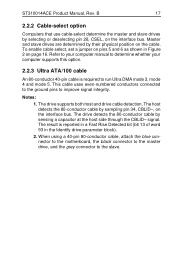
... Ultra DMA mode 3, mode 4 and mode 5. signal. ST310014ACE Product Manual, Rev. This cable uses even-numbered conductors connected to the ground pins to the slave. The drive supports both host and drive cable detection. B 17 2.2.2 Cable-select option Computers that use cable-select determine the master and slave drives by sensing a capacitor at the host side through the CBLID- To enable cable select, set a jumper on page 16. Master and slave drives are determined by sampling pin 34, CBLID-, on the cable. The host...
... Ultra DMA mode 3, mode 4 and mode 5. signal. ST310014ACE Product Manual, Rev. This cable uses even-numbered conductors connected to the ground pins to the slave. The drive supports both host and drive cable detection. B 17 2.2.2 Cable-select option Computers that use cable-select determine the master and slave drives by sensing a capacitor at the host side through the CBLID- To enable cable select, set a jumper on page 16. Master and slave drives are determined by sampling pin 34, CBLID-, on the cable. The host...
Product Manual
Page 29
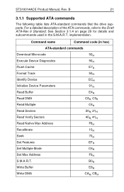
See Section 3.1.4 on page 29 for details and subcommands used in hex) ATA-standard commands Download Microcode Execute Device Diagnostics Flush Cache Format Track Identify Device Initialize Device Parameters Read Buffer Read DMA Read Multiple Read Sectors Read Verify Sectors Read Native Max Address Recalibrate Seek Set Features Set Multiple Mode Set Max Address S.M.A.R.T. implementation. Write Buffer Write DMA 92H 90H E7H 50H ECH 91H E4H C8H, C9H C4H 20H, 21H 40H, 41H F8H 10H 70H EFH C6H F9H...
See Section 3.1.4 on page 29 for details and subcommands used in hex) ATA-standard commands Download Microcode Execute Device Diagnostics Flush Cache Format Track Identify Device Initialize Device Parameters Read Buffer Read DMA Read Multiple Read Sectors Read Verify Sectors Read Native Max Address Recalibrate Seek Set Features Set Multiple Mode Set Max Address S.M.A.R.T. implementation. Write Buffer Write DMA 92H 90H E7H 50H ECH 91H E4H C8H, C9H C4H 20H, 21H 40H, 41H F8H 10H 70H EFH C6H F9H...
Product Manual
Page 30
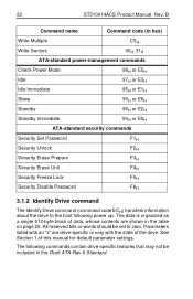
... ATA-standard security commands Security Set Password F1H Security Unlock F2H Security Erase Prepare F3H Security Erase Unit F4H Security Freeze Lock F5H Security Disable Password F6H 3.1.2 Identify Drive command The Identify Drive command (command code ECH) transfers information about the drive to zero. See Section 1 of the drive. B Command name Command code (in the table on page 25. The data is organized as a single 512-byte block of data, whose contents are drive-specific or vary with the state of this manual for default parameter settings. 22 ST310014ACE Product...
... ATA-standard security commands Security Set Password F1H Security Unlock F2H Security Erase Prepare F3H Security Erase Unit F4H Security Freeze Lock F5H Security Disable Password F6H 3.1.2 Identify Drive command The Identify Drive command (command code ECH) transfers information about the drive to zero. See Section 1 of the drive. B Command name Command code (in the table on page 25. The data is organized as a single 512-byte block of data, whose contents are drive-specific or vary with the state of this manual for default parameter settings. 22 ST310014ACE Product...
Product Manual
Page 31
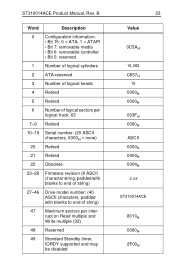
...: 0 = ATA; 1 = ATAPI • Bit 7: removable media • Bit 6: removable controller • Bit 0: reserved 1 Number of logical cylinders 2 ATA-reserved 3 Number of logical heads 4 Retired 5 Retired 6 Number of logical sectors per logical track: 63 7-9 Retired 10-19 20 Serial number: (20 ASCII characters, 0000H = none) Retired 21 Retired 22 Obsolete 23-26 Firmware revision (8 ASCII character string, padded with blanks to end of string) 27-46 Drive model number...
...: 0 = ATA; 1 = ATAPI • Bit 7: removable media • Bit 6: removable controller • Bit 0: reserved 1 Number of logical cylinders 2 ATA-reserved 3 Number of logical heads 4 Retired 5 Retired 6 Number of logical sectors per logical track: 63 7-9 Retired 10-19 20 Serial number: (20 ASCII characters, 0000H = none) Retired 21 Retired 22 Obsolete 23-26 Firmware revision (8 ASCII character string, padded with blanks to end of string) 27-46 Drive model number...

Product Manual
Page 35
... the drive supports, the command is currently active. The acceptable values for the Features register are defined as follows: 02H Enable write cache (default). 03H Set transfer mode (based on value in the register does not represent a feature that the drive supports. If the value in Sector Count register). ST310014ACE Product Manual, Rev. B 27 3 Ultra DMA mode 3 is supported. 4 Ultra DMA mode 4 is supported. 5 Ultra DMA mode 5 is supported. 8 Ultra DMA mode 0 is...
... the drive supports, the command is currently active. The acceptable values for the Features register are defined as follows: 02H Enable write cache (default). 03H Set transfer mode (based on value in the register does not represent a feature that the drive supports. If the value in Sector Count register). ST310014ACE Product Manual, Rev. B 27 3 Ultra DMA mode 3 is supported. 4 Ultra DMA mode 4 is supported. 5 Ultra DMA mode 5 is supported. 8 Ultra DMA mode 0 is...

Product Manual
Page 37
... Error register. commands and implementation, see the Draft ATA-Rev 6 Standard. SeaTools diagnostic software activates a built-in Features S.M.A.R.T. Read Data D1H Obsolete D2H S.M.A.R.T. Disable Operations S.M.A.R.T. Enable/Disable Attribute Autosave D3H S.M.A.R.T. Return Status Note. Enable Operations S.M.A.R.T. is written to enable this feature. The table below shows the S.M.A.R.T. Read Log Sector S.M.A.R.T. ST310014ACE Product Manual, Rev. features disabled. You must have a recent BIOS or software package that supports S.M.A.R.T. If an appropriate code...
... Error register. commands and implementation, see the Draft ATA-Rev 6 Standard. SeaTools diagnostic software activates a built-in Features S.M.A.R.T. Read Data D1H Obsolete D2H S.M.A.R.T. Disable Operations S.M.A.R.T. Enable/Disable Attribute Autosave D3H S.M.A.R.T. Return Status Note. Enable Operations S.M.A.R.T. is written to enable this feature. The table below shows the S.M.A.R.T. Read Log Sector S.M.A.R.T. ST310014ACE Product Manual, Rev. features disabled. You must have a recent BIOS or software package that supports S.M.A.R.T. If an appropriate code...


