
ST1.2 Series Product Manual
Page 2
...: 100375652, Rev. One gigabyte, or GB, equals one of Seagate Technology LLC or one billion bytes when referring to change, without notice, product offerings or specifications. Actual quantities will vary based on operating environment and formatting. Seagate reserves the right to hard drive capacity. Copyright © 2005 - 2007 Seagate Technology LLC. ST1.2 Series, SeaTools and SeaTDD are either...
...: 100375652, Rev. One gigabyte, or GB, equals one of Seagate Technology LLC or one billion bytes when referring to change, without notice, product offerings or specifications. Actual quantities will vary based on operating environment and formatting. Seagate reserves the right to hard drive capacity. Copyright © 2005 - 2007 Seagate Technology LLC. ST1.2 Series, SeaTools and SeaTDD are either...
ST1.2 Series Product Manual
Page 3
Contents 1.0 Introduction 1 1.1 Disclaimer 2 1.2 Drive care 2 1.3 Handling precautions 2 2.0 Drive specifications 3 2.1 Power, access times and acoustics 3 2.2 ...drive 21 3.1 Handling and static discharge precautions 21 3.2 Drive installation 22 4.0 Interface description 25 4.1 Connector interface signals and connector pins 25 4.1.1 Flex interface connector signals 27 4.1.2 Supported ATA commands 29 4.1.3 Identify Device command 31 4.1.4 Set Features command 35 4.1.5 Card Information Structure (CIS) information for CF 37 5.0 Seagate Technology support services 49 ST1.2 Series...
Contents 1.0 Introduction 1 1.1 Disclaimer 2 1.2 Drive care 2 1.3 Handling precautions 2 2.0 Drive specifications 3 2.1 Power, access times and acoustics 3 2.2 ...drive 21 3.1 Handling and static discharge precautions 21 3.2 Drive installation 22 4.0 Interface description 25 4.1 Connector interface signals and connector pins 25 4.1.1 Flex interface connector signals 27 4.1.2 Supported ATA commands 29 4.1.3 Identify Device command 31 4.1.4 Set Features command 35 4.1.5 Card Information Structure (CIS) information for CF 37 5.0 Seagate Technology support services 49 ST1.2 Series...
ST1.2 Series Product Manual
Page 5
.... Figure 11. Figure 4. Figure 7. Figure 9. Figure 6. ST1.2 Series CompactFlash+ disc drive 1 ST1.2 Series Flex (IDE interface) disc drive 1 ST1.2 Series breather hole location 2 ST1.2 Series improper handling example 2 Typical 3.3V startup and operation current profile 8 Location where tri-axial accelerometer will be placed on ST1.2 drive 12 Drive axis definition for ST1.2 drives 12 ST1.2 Series proper handling example 21 ST1.2 Series improper handling example 21 CF model mechanical...
.... Figure 11. Figure 4. Figure 7. Figure 9. Figure 6. ST1.2 Series CompactFlash+ disc drive 1 ST1.2 Series Flex (IDE interface) disc drive 1 ST1.2 Series breather hole location 2 ST1.2 Series improper handling example 2 Typical 3.3V startup and operation current profile 8 Location where tri-axial accelerometer will be placed on ST1.2 drive 12 Drive axis definition for ST1.2 drives 12 ST1.2 Series proper handling example 21 ST1.2 Series improper handling example 21 CF model mechanical...
ST1.2 Series Product Manual
Page 7
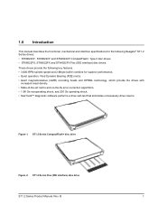
... operating shock. • SeaTools™ diagnostic software performs a drive self-test that eliminates unnecessary drive returns. These drives provide the following key features. • 3,600-RPM spindle speed and 2-Mbyte buffer combine for the following Seagate® ST1.2 Series drives: • ST68022CF, ST66022CF and ST64022CF CompactFlash+ Type II disc drives. • ST68022FX, ST66022FX and ST64022FX Flex (IDE interface...
... operating shock. • SeaTools™ diagnostic software performs a drive self-test that eliminates unnecessary drive returns. These drives provide the following key features. • 3,600-RPM spindle speed and 2-Mbyte buffer combine for the following Seagate® ST1.2 Series drives: • ST68022CF, ST66022CF and ST64022CF CompactFlash+ Type II disc drives. • ST68022FX, ST66022FX and ST64022FX Flex (IDE interface...

ST1.2 Series Product Manual
Page 8
...device immediately after operation. 2 ST1.2 Series Product Manual, Rev. Be careful when removing the drive from shock, vibration, or electrostatic discharge (ESD). • Handle the drive carefully by the edges. Doing so may result in Section 2.8, "Environmental specifications." ST1.2 Series breather hole location •...damage. 1.2 Drive care Do not use the ST1.2 Series disc drives outside of the ranges of environmental conditions found in loss of data. procurement of force to the drive during operation. Do not touch any force to the top cover. Seagate may become ...
...device immediately after operation. 2 ST1.2 Series Product Manual, Rev. Be careful when removing the drive from shock, vibration, or electrostatic discharge (ESD). • Handle the drive carefully by the edges. Doing so may result in Section 2.8, "Environmental specifications." ST1.2 Series breather hole location •...damage. 1.2 Drive care Do not use the ST1.2 Series disc drives outside of the ranges of environmental conditions found in loss of data. procurement of force to the drive during operation. Do not touch any force to the top cover. Seagate may become ...
ST1.2 Series Product Manual
Page 9
...inches) 18.0 grams (0.0397 lb.) 8.3 1.2 / 2.5 1.0 / 2.5 350 mA 226 mA 330 mA 200 mA 90 mA ST1.2 Series Product Manual, Rev. Table 1: Specifications Drive specification Formatted Gbytes Guaranteed sectors Bytes per sector Cache (Mbytes) Recording density, BPI (bits/inch max) Track density. B 3 For ... 11,719,008 7,999,488 1024 2 663,000 110,000 72.9 3,600 130.0 8.8 33.3MB/s (UDMA 2) PIO modes 0-4; 2.0 Drive specifications Unless otherwise noted, all specifications are for quick reference. For details on to ready (sec typical / max) (without retry) Startup current ...
...inches) 18.0 grams (0.0397 lb.) 8.3 1.2 / 2.5 1.0 / 2.5 350 mA 226 mA 330 mA 200 mA 90 mA ST1.2 Series Product Manual, Rev. Table 1: Specifications Drive specification Formatted Gbytes Guaranteed sectors Bytes per sector Cache (Mbytes) Recording density, BPI (bits/inch max) Track density. B 3 For ... 11,719,008 7,999,488 1024 2 663,000 110,000 72.9 3,600 130.0 8.8 33.3MB/s (UDMA 2) PIO modes 0-4; 2.0 Drive specifications Unless otherwise noted, all specifications are for quick reference. For details on to ready (sec typical / max) (without retry) Startup current ...

ST1.2 Series Product Manual
Page 10
B Table 1: Specifications Drive specification ST68022CF ST68022FX ST66022CF ST66022FX ST64022CF ST64022FX Standby/Sleep mode (typical 3.3V) 30 mA Voltage tolerance (including noise) 3.3V ± 5% 5V ± 10% Ambient...rate Drive acoustics, sound power (bels) Idle (typical / max) 2.1/ 2.4 Operational (typical / max) 2.2 / 2.5 Nonrecoverable read errors Annualized Failure Rate Load/Unload (LUL) cycles (40°C) Warranty 1 per 1014 bits read 0.4% AFR at 25°C 300,000 software-controlled power on/off cycles 20,000 hard power on/off cycles Per agreement 4 ST1.2 Series ...
B Table 1: Specifications Drive specification ST68022CF ST68022FX ST66022CF ST66022FX ST64022CF ST64022FX Standby/Sleep mode (typical 3.3V) 30 mA Voltage tolerance (including noise) 3.3V ± 5% 5V ± 10% Ambient...rate Drive acoustics, sound power (bels) Idle (typical / max) 2.1/ 2.4 Operational (typical / max) 2.2 / 2.5 Nonrecoverable read errors Annualized Failure Rate Load/Unload (LUL) cycles (40°C) Warranty 1 per 1014 bits read 0.4% AFR at 25°C 300,000 software-controlled power on/off cycles 20,000 hard power on/off cycles Per agreement 4 ST1.2 Series ...
ST1.2 Series Product Manual
Page 11
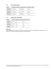
... ST64022CF ST64022FX Cylinders Read/write heads Sectors per track 15,501 16 63 11,626 16 63 7,936 16 63 LBA mode When addressing these drives in LBA mode, all blocks (sectors) are consecutively numbered from 0 to n-1, where n is the number of guaranteed sectors as defined above. B 5 ST1.2 Series Product Manual, Rev.
... ST64022CF ST64022FX Cylinders Read/write heads Sectors per track 15,501 16 63 11,626 16 63 7,936 16 63 LBA mode When addressing these drives in LBA mode, all blocks (sectors) are consecutively numbered from 0 to n-1, where n is the number of guaranteed sectors as defined above. B 5 ST1.2 Series Product Manual, Rev.

ST1.2 Series Product Manual
Page 13
... from/to the parked position. • Standby mode / Sleep mode During Standby mode, the drive accepts commands, but the drive is not spinning, and the servo and read or write operation. ST1.2 Series Product Manual, Rev. 2.7 Power specifications The drive receives DC power (+3.3V or +5V) through the CompactFlash interface connector for ST68022CF, ST66022CF and...
... from/to the parked position. • Standby mode / Sleep mode During Standby mode, the drive accepts commands, but the drive is not spinning, and the servo and read or write operation. ST1.2 Series Product Manual, Rev. 2.7 Power specifications The drive receives DC power (+3.3V or +5V) through the CompactFlash interface connector for ST68022CF, ST66022CF and...

ST1.2 Series Product Manual
Page 14
B Typical 3.3V startup and operation current profile 8 ST1.2 Series Product Manual, Rev. Table 2: DC power ST1 Power Consumption (W) Max current the average of the peak value in 10ms window Current Spinup Load/Unload current Write Read Seek Performance idle Low power ... 300 350 350 300 Average 5.0V (mA) 330 340 226 205 92 33 Max 5.0V (mA) 350 300 300 350 350 300 *During periods of drive idle, some offline activity may increase acoustic and power to the S.M.A.R.T. specification, which may occur according to operational levels. 2.7.1.1 Typical current profile Figure 5.
B Typical 3.3V startup and operation current profile 8 ST1.2 Series Product Manual, Rev. Table 2: DC power ST1 Power Consumption (W) Max current the average of the peak value in 10ms window Current Spinup Load/Unload current Write Read Seek Performance idle Low power ... 300 350 350 300 Average 5.0V (mA) 330 340 226 205 92 33 Max 5.0V (mA) 350 300 300 350 350 300 *During periods of drive idle, some offline activity may increase acoustic and power to the S.M.A.R.T. specification, which may occur according to operational levels. 2.7.1.1 Typical current profile Figure 5.

ST1.2 Series Product Manual
Page 15
... expected to operate with a maximum of 70 mV peak-to-peak square-wave injected noise at up to 20 MHz. B 9 Using 3.3-volt power, the drive is expected to operate with a maximum of 100 mV peak-to-peak square-wave injected noise at up to 20 MHz. 2.7.2 Conducted noise Input noise ... is calculated by dividing the nominal voltage by the typical RMS read/write current. 2.7.3 Voltage tolerance Voltage tolerance (including noise): 5.0V ± 10% 3.3V ± 5% ST1.2 Series Product Manual, Rev. Note.
... expected to operate with a maximum of 70 mV peak-to-peak square-wave injected noise at up to 20 MHz. B 9 Using 3.3-volt power, the drive is expected to operate with a maximum of 100 mV peak-to-peak square-wave injected noise at up to 20 MHz. 2.7.2 Conducted noise Input noise ... is calculated by dividing the nominal voltage by the typical RMS read/write current. 2.7.3 Voltage tolerance Voltage tolerance (including noise): 5.0V ± 10% 3.3V ± 5% ST1.2 Series Product Manual, Rev. Note.

ST1.2 Series Product Manual
Page 16
... Idle, low power Standby/Sleep Heads Tracking Parked Parked Spindle Rotating Rotating Stopped Buffer Enabled Disabled Disabled • Active mode The drive is in Active mode during the read , write or seek), the standby timer is reinitialized and begins counting down from Active ... is set the standby timer, the drive can also enter Standby mode automatically after the drive has been inactive for a specifiable length of time. 2.7.4 Power-management modes The drive provides programmable power management to Active mode when disc access is necessary. 10 ST1.2 Series Product Manual, Rev.
... Idle, low power Standby/Sleep Heads Tracking Parked Parked Spindle Rotating Rotating Stopped Buffer Enabled Disabled Disabled • Active mode The drive is in Active mode during the read , write or seek), the standby timer is reinitialized and begins counting down from Active ... is set the standby timer, the drive can also enter Standby mode automatically after the drive has been inactive for a specifiable length of time. 2.7.4 Power-management modes The drive provides programmable power management to Active mode when disc access is necessary. 10 ST1.2 Series Product Manual, Rev.

ST1.2 Series Product Manual
Page 17
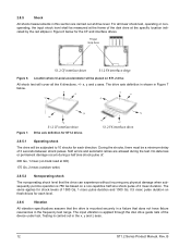
Actual drive case temperature should not exceed 70°C (158°F) within the operating ambient conditions. Operating 0° to 70°C (41° to 158°F) ...per hour (86°F per hour max), without condensation 2.8.3 Humidity 2.8.3.1 Relative humidity Operating 5% to 90% noncondensing (30% per hour max) Nonoperating 5% to 40,000+ ft) ST1.2 Series Product Manual, Rev. 2.8 Environmental specifications 2.8.1 Ambient temperature Ambient temperature is derated linearly by the nonoperating Temperature and the Relative Humidity levels. 2.8.4 Altitude Operating -60.98...
Actual drive case temperature should not exceed 70°C (158°F) within the operating ambient conditions. Operating 0° to 70°C (41° to 158°F) ...per hour (86°F per hour max), without condensation 2.8.3 Humidity 2.8.3.1 Relative humidity Operating 5% to 90% noncondensing (30% per hour max) Nonoperating 5% to 40,000+ ft) ST1.2 Series Product Manual, Rev. 2.8 Environmental specifications 2.8.1 Ambient temperature Ambient temperature is derated linearly by the nonoperating Temperature and the Relative Humidity levels. 2.8.4 Altitude Operating -60.98...
ST1.2 Series Product Manual
Page 18
...7. +y +x +z S1.2 CF interface drive Drive axis definition for ST1.2 drives +y +x +z S1.2 FX interface drive 2.8.5.1 Operating shock The drive will be subjected to 10 shocks for the CF and interface drives. The input vibration is carried out in the x, y and z axes. 12 ST1.2 Series Product Manual, Rev. Testing is applied ...through the disc drive guide rails of the device under test. For...
...7. +y +x +z S1.2 CF interface drive Drive axis definition for ST1.2 drives +y +x +z S1.2 FX interface drive 2.8.5.1 Operating shock The drive will be subjected to 10 shocks for the CF and interface drives. The input vibration is carried out in the x, y and z axes. 12 ST1.2 Series Product Manual, Rev. Testing is applied ...through the disc drive guide rails of the device under test. For...

ST1.2 Series Product Manual
Page 19
... consist of random vibration using the power spectral density (PSD) levels specified in the table below. ST1.2 Series Product Manual, Rev. The drive will operate without a hard error while being subjected to the following vibration levels. Table 4: Operating random vibration profile Frequency (Hz) G2/Hz 17 1.1 x E-03 45 1.1... experience while meeting the performance standards specified. B 13 The vibration test level is 0.67 Gs RMS. The drive will operate without a hard error while being subjected to the following vibration levels. 5 Hz to 500 Hz @ 2 oct/min 1.0 Gs (0...
... consist of random vibration using the power spectral density (PSD) levels specified in the table below. ST1.2 Series Product Manual, Rev. The drive will operate without a hard error while being subjected to the following vibration levels. Table 4: Operating random vibration profile Frequency (Hz) G2/Hz 17 1.1 x E-03 45 1.1... experience while meeting the performance standards specified. B 13 The vibration test level is 0.67 Gs RMS. The drive will operate without a hard error while being subjected to the following vibration levels. 5 Hz to 500 Hz @ 2 oct/min 1.0 Gs (0...

ST1.2 Series Product Manual
Page 20
... 1.8 x E-02 2.8.6.5 Corrosive environment Seagate electronic drive components pass accelerated corrosion testing equivalent to ten years of sulfide, chloride, and nitrate contaminants. The silver, copper, nickel and gold films used in the table below. Materials used in Seagate products are especially sensitive to the presence... ASTM B845. Sulfur is 3.01 Gs RMS. The drive will not incur any electronic components to be affected by replacing materials near circuitry with sulfide-free alternatives. 14 ST1.2 Series Product Manual, Rev. B However, this accelerated testing cannot...
... 1.8 x E-02 2.8.6.5 Corrosive environment Seagate electronic drive components pass accelerated corrosion testing equivalent to ten years of sulfide, chloride, and nitrate contaminants. The silver, copper, nickel and gold films used in the table below. Materials used in Seagate products are especially sensitive to the presence... ASTM B845. Sulfur is 3.01 Gs RMS. The drive will not incur any electronic components to be affected by replacing materials near circuitry with sulfide-free alternatives. 14 ST1.2 Series Product Manual, Rev. B However, this accelerated testing cannot...

ST1.2 Series Product Manual
Page 21
...bels (max) Operational 2.2 bels (typ) 2.5 bels (max) 2.10 Electromagnetic immunity When properly installed in a representative host system, the drive operates without errors or degradation in performance when subjected to the radio frequency (RF) environments defined in the following equation: (Number of ... EN 61000-4-5: 95 EN 61000-4-6: 97 EN 61000-4-11: 94 ST1.2 Series Product Manual, Rev. All measurements are taken under essentially free-field conditions over a reflecting plane. B 15 Note. 2.9 Acoustics Drive acoustics are added to the A-weighted sound power (LW) with ...
...bels (max) Operational 2.2 bels (typ) 2.5 bels (max) 2.10 Electromagnetic immunity When properly installed in a representative host system, the drive operates without errors or degradation in performance when subjected to the radio frequency (RF) environments defined in the following equation: (Number of ... EN 61000-4-5: 95 EN 61000-4-6: 97 EN 61000-4-11: 94 ST1.2 Series Product Manual, Rev. All measurements are taken under essentially free-field conditions over a reflecting plane. B 15 Note. 2.9 Acoustics Drive acoustics are added to the A-weighted sound power (LW) with ...
ST1.2 Series Product Manual
Page 23
...E-H011-05-2175(B) • Trade name or applicant: Seagate Technology International • Manufacturing date: May 2005 • Manufacturer/nationality: Seagate Technology International Australian C-Tick (N176) If these drives have been tested and comply with the Electromagnetic Interference/Electromagnetic... by TUV Essen. 2.12.2 Electromagnetic compatibility Hard drives that display the CE mark comply with the European Union (EU) requirements specified in electronic products, effective July 2006. ST1.2 Series Product Manual, Rev. Drives are tested in a representative, end-user ...
...E-H011-05-2175(B) • Trade name or applicant: Seagate Technology International • Manufacturing date: May 2005 • Manufacturer/nationality: Seagate Technology International Australian C-Tick (N176) If these drives have been tested and comply with the Electromagnetic Interference/Electromagnetic... by TUV Essen. 2.12.2 Electromagnetic compatibility Hard drives that display the CE mark comply with the European Union (EU) requirements specified in electronic products, effective July 2006. ST1.2 Series Product Manual, Rev. Drives are tested in a representative, end-user ...

ST1.2 Series Product Manual
Page 24
... uses radio frequency energy and if not installed and used in a particular installation. "X RoHS MCV 2.12.5 FCC verification These drives are intended to radio and television reception. Operation with the limits for Control of 20 years. However, there is no Federal ... is over the threshold defined by turning the equipment on and off, you are on different branch outlets. 18 ST1.2 Series Product Manual, Rev. B Seagate Technology LLC has tested this equipment does cause interference to radio or television, which can be contained solely within a...
... uses radio frequency energy and if not installed and used in a particular installation. "X RoHS MCV 2.12.5 FCC verification These drives are intended to radio and television reception. Operation with the limits for Control of 20 years. However, there is no Federal ... is over the threshold defined by turning the equipment on and off, you are on different branch outlets. 18 ST1.2 Series Product Manual, Rev. B Seagate Technology LLC has tested this equipment does cause interference to radio or television, which can be contained solely within a...

ST1.2 Series Product Manual
Page 27
... you mount it with care. Do not press down on the drive top cover or attempt to use a pen to the top cover. ST1.2 Series proper handling example • The drive is plugged into a grounded outlet. ST1.2 Series Product Manual, Rev. 3.0 Configuring and mounting the drive This section contains the specifications and instructions for installation to limit...
... you mount it with care. Do not press down on the drive top cover or attempt to use a pen to the top cover. ST1.2 Series proper handling example • The drive is plugged into a grounded outlet. ST1.2 Series Product Manual, Rev. 3.0 Configuring and mounting the drive This section contains the specifications and instructions for installation to limit...


