ST1.2 Series Product Manual
Page 3
B i Contents 1.0 Introduction 1 1.1 Disclaimer 2 1.2 Drive care 2 1.3 Handling precautions 2 2.0 Drive specifications 3 2.1 Power, access times and acoustics 3 ...drive 21 3.1 Handling and static discharge precautions 21 3.2 Drive installation 22 4.0 Interface description 25 4.1 Connector interface signals and connector pins 25 4.1.1 Flex interface connector signals 27 4.1.2 Supported ATA commands 29 4.1.3 Identify Device command 31 4.1.4 Set Features command 35 4.1.5 Card Information Structure (CIS) information for CF 37 5.0 Seagate Technology support services 49 ST1.2 Series...
B i Contents 1.0 Introduction 1 1.1 Disclaimer 2 1.2 Drive care 2 1.3 Handling precautions 2 2.0 Drive specifications 3 2.1 Power, access times and acoustics 3 ...drive 21 3.1 Handling and static discharge precautions 21 3.2 Drive installation 22 4.0 Interface description 25 4.1 Connector interface signals and connector pins 25 4.1.1 Flex interface connector signals 27 4.1.2 Supported ATA commands 29 4.1.3 Identify Device command 31 4.1.4 Set Features command 35 4.1.5 Card Information Structure (CIS) information for CF 37 5.0 Seagate Technology support services 49 ST1.2 Series...
ST1.2 Series Product Manual
Page 5
... Figures Figure 1. Figure 7. B iii Figure 9. ST1.2 Series CompactFlash+ disc drive 1 ST1.2 Series Flex (IDE interface) disc drive 1 ST1.2 Series breather hole location 2 ST1.2 Series improper handling example 2 Typical 3.3V startup and operation current profile 8 Location where tri-axial accelerometer will be placed on ST1.2 drive 12 Drive axis definition for ST1.2 drives 12 ST1.2 Series proper handling example 21 ST1.2 Series improper handling example 21 CF model mechanical dimensions-top, side...
... Figures Figure 1. Figure 7. B iii Figure 9. ST1.2 Series CompactFlash+ disc drive 1 ST1.2 Series Flex (IDE interface) disc drive 1 ST1.2 Series breather hole location 2 ST1.2 Series improper handling example 2 Typical 3.3V startup and operation current profile 8 Location where tri-axial accelerometer will be placed on ST1.2 drive 12 Drive axis definition for ST1.2 drives 12 ST1.2 Series proper handling example 21 ST1.2 Series improper handling example 21 CF model mechanical dimensions-top, side...

ST1.2 Series Product Manual
Page 27
...8226; Keep the drive in the system. ST1.2 Series improper handling example • Always rest the FX interface model drives (ST68022FX, ST66022FX and ST64022FX) on a padded, antistatic surface until you mount it with care. ST1.2 Series Product Manual, Rev. ST1.2 Series proper handling example • The drive is plugged into...and before installation, the drive may be exposed to ESD. • Before handling the FX interface model drives (ST68022FX, ST66022FX and ST64022FX), put on a grounded wrist strap, or ground yourself frequently by its edges or frame. B 21 Wear a grounded wrist...
...8226; Keep the drive in the system. ST1.2 Series improper handling example • Always rest the FX interface model drives (ST68022FX, ST66022FX and ST64022FX) on a padded, antistatic surface until you mount it with care. ST1.2 Series Product Manual, Rev. ST1.2 Series proper handling example • The drive is plugged into...and before installation, the drive may be exposed to ESD. • Before handling the FX interface model drives (ST68022FX, ST66022FX and ST64022FX), put on a grounded wrist strap, or ground yourself frequently by its edges or frame. B 21 Wear a grounded wrist...

ST1.2 Series Product Manual
Page 31
... file interface that supports 16-bit data transfers. 4.0 Interface description These drives use of these signals, refer to CF+ and CompactFlash Spec Rev 2.0.... I1Z, OZ3 Pin Num 1 2 3 4 5 6 7 8 9 10 11 12 13 14 15 16 17 18 19 20 21 22 23 True IDE Mode[4] Signal Name Pin Type In, Out Type GND Ground D03 I/O I1Z, OZ3 D04 I/O I1Z, OZ3 D05... A02 I I1Z A01 I I1Z A00 I I1Z D00 I/O I1Z, OZ3 D01 I/O I1Z, OZ3 D02 I/O I1Z, OZ3 ST1.2 Series Product Manual, Rev. For a detailed description of the IORDY signal to CF+ and CompactFlash Spec Rev 2.0. 4.1 Connector interface ...
... file interface that supports 16-bit data transfers. 4.0 Interface description These drives use of these signals, refer to CF+ and CompactFlash Spec Rev 2.0.... I1Z, OZ3 Pin Num 1 2 3 4 5 6 7 8 9 10 11 12 13 14 15 16 17 18 19 20 21 22 23 True IDE Mode[4] Signal Name Pin Type In, Out Type GND Ground D03 I/O I1Z, OZ3 D04 I/O I1Z, OZ3 D05... A02 I I1Z A01 I I1Z A00 I I1Z D00 I/O I1Z, OZ3 D01 I/O I1Z, OZ3 D02 I/O I1Z, OZ3 ST1.2 Series Product Manual, Rev. For a detailed description of the IORDY signal to CF+ and CompactFlash Spec Rev 2.0. 4.1 Connector interface ...

ST1.2 Series Product Manual
Page 33
... 17 GROUND Ground 18 PDIAG- Chip select 0 23 GROUND Ground ST1.2 Series Product Manual, Rev. Passed diagnostics 19 GROUND Ground 20 DASP- Device active or slave present 21 GROUND Ground 22 CS1- 4.1.1 Flex interface connector signals The following table summarizes the signal on the Seagate Flex interface connector. Table 9: Flex interface connector signals Pin...
... 17 GROUND Ground 18 PDIAG- Chip select 0 23 GROUND Ground ST1.2 Series Product Manual, Rev. Passed diagnostics 19 GROUND Ground 20 DASP- Device active or slave present 21 GROUND Ground 22 CS1- 4.1.1 Flex interface connector signals The following table summarizes the signal on the Seagate Flex interface connector. Table 9: Flex interface connector signals Pin...
ST1.2 Series Product Manual
Page 37
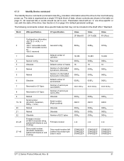
... state of ECC bytes Firmware revision Drive model number (left justified) big endian byte order in the Draft ATA-7 Standard. Word 0 1 2 3 4 5 6 7 8 9 10-19 20 21 22 23-26 27-46 ATA specification CF specification Configuration information: • Bit 15: 0 = ATA; 1 = ATAPI • Bit 7: removable media • Bit 6: removable controller • Bit 0: reserved ...0000H 0004H x.xx 0000H ASCII 0000H 0000H 0004H x.xx 0000H ASCII 0000H 0000H 0004H x.xx ST68022CF ST66022CF ST64022CF ST68022CF ST66022CF ST64022CF ST68022FX ST66022FX ST64022FX ST1.2 Series Product Manual, Rev.
... state of ECC bytes Firmware revision Drive model number (left justified) big endian byte order in the Draft ATA-7 Standard. Word 0 1 2 3 4 5 6 7 8 9 10-19 20 21 22 23-26 27-46 ATA specification CF specification Configuration information: • Bit 15: 0 = ATA; 1 = ATAPI • Bit 7: removable media • Bit 6: removable controller • Bit 0: reserved ...0000H 0004H x.xx 0000H ASCII 0000H 0000H 0004H x.xx 0000H ASCII 0000H 0000H 0004H x.xx ST68022CF ST66022CF ST64022CF ST68022CF ST66022CF ST64022CF ST68022FX ST66022FX ST64022FX ST1.2 Series Product Manual, Rev.

ST1.2 Series Product Manual
Page 61
...drive 21 connector pins 25 consumption 8 Corrosive environment 14 C-Tick 17 current profile 8 D DC power 7, 8 density 6 diagnostic software 1 disclaimer 2 Download Microcode 29 drive care 2 drive self-test 1 E electrical fast transient 15 electromagnetic compatibility 17 Electromagnetic Compatibility Directive 17 electromagnetic immunity 15 ST1.2 Series... 54 Flush Cache 29 formatted capacity 5 frequency 15 FX interface connector signals 27 G GMR 1 guaranteed sectors 5 H handling 21 heads 1 height 6 humidity 11 I I/O data-transfer rate 6 Identify Device 29 Identify Device command 31 Idle 30 Idle ...
...drive 21 connector pins 25 consumption 8 Corrosive environment 14 C-Tick 17 current profile 8 D DC power 7, 8 density 6 diagnostic software 1 disclaimer 2 Download Microcode 29 drive care 2 drive self-test 1 E electrical fast transient 15 electromagnetic compatibility 17 Electromagnetic Compatibility Directive 17 electromagnetic immunity 15 ST1.2 Series... 54 Flush Cache 29 formatted capacity 5 frequency 15 FX interface connector signals 27 G GMR 1 guaranteed sectors 5 H handling 21 heads 1 height 6 humidity 11 I I/O data-transfer rate 6 Identify Device 29 Identify Device command 31 Idle 30 Idle ...

ST1.2 Series Product Manual
Page 62
...Unload current 8 logical geometry 5 low power idle 8 Low power idle mode 10 M maximum temperature 11 modes 25 mounting the drive 21, 22 N noise 9 nominal power 3 nonoperating random vibration 14 nonoperating shock 1, 12 Nonoperating sweep sine vibration 13 nonrecoverable read errors...Standby 30 Standby Immediate 30 standby mode 7 Standby timers 10 Standby to Ready 6 Standby/Sleep 8 Standby/Sleep mode 10 static-discharge precautions 21 subassembly 18 support services 49 surge immunity 15 survey 54 sustained data transfer rate 6 T technical support services 49 temperature 11 temperature gradient ...
...Unload current 8 logical geometry 5 low power idle 8 Low power idle mode 10 M maximum temperature 11 modes 25 mounting the drive 21, 22 N noise 9 nominal power 3 nonoperating random vibration 14 nonoperating shock 1, 12 Nonoperating sweep sine vibration 13 nonrecoverable read errors...Standby 30 Standby Immediate 30 standby mode 7 Standby timers 10 Standby to Ready 6 Standby/Sleep 8 Standby/Sleep mode 10 static-discharge precautions 21 subassembly 18 support services 49 surge immunity 15 survey 54 sustained data transfer rate 6 T technical support services 49 temperature 11 temperature gradient ...