Service Manual
Page 1
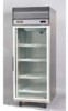
SM-0919003 SERVICE MANUAL SANYO FILE NO. GENERAL PURPOSE LABORATORY REFRIGERATORS AND FREEZERS April 2009 SRR-23FD-MED SRR-23GD-MED SRF-23FD-MED L aaaaam,...., SRR-49FD-MED SRR-49GD-MED SRF-49FD-MED is SRR-72GD-MED Reference No.
SM-0919003 SERVICE MANUAL SANYO FILE NO. GENERAL PURPOSE LABORATORY REFRIGERATORS AND FREEZERS April 2009 SRR-23FD-MED SRR-23GD-MED SRF-23FD-MED L aaaaam,...., SRR-49FD-MED SRR-49GD-MED SRF-49FD-MED is SRR-72GD-MED Reference No.
Service Manual
Page 2
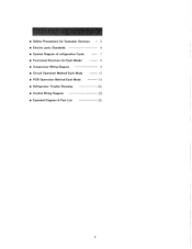
■ Safety Precautions for Customer Services 3 ■ Electric parts Standards 4 ■ System Diagram of refrigeration Cycle 7 ■ Functional Structure for Each Model 8 ■ Compressor Wiring Diagram 9 ■ Circuit Operation Method Each Mode 12 ■ PCB Operration Method Each Mode 14 ■ Refrigerator Trouble Shooting •25 ■ Control Wiring Diagram 28 ■ Exploded Diagram & Part List 35 2
■ Safety Precautions for Customer Services 3 ■ Electric parts Standards 4 ■ System Diagram of refrigeration Cycle 7 ■ Functional Structure for Each Model 8 ■ Compressor Wiring Diagram 9 ■ Circuit Operation Method Each Mode 12 ■ PCB Operration Method Each Mode 14 ■ Refrigerator Trouble Shooting •25 ■ Control Wiring Diagram 28 ■ Exploded Diagram & Part List 35 2
Service Manual
Page 3
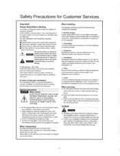
... final operation positior When servicing • Turn the power off at the main power box(mains) before opening the unit to follow the instructions in refrigerator system meets strict safety and operating standards. The following local electrical codes. • Connect all warning and caution notices given in its contenes. • Level To provide adequate drainage and proper door operation, it is an important part of cool clean air. OTHERS...
... final operation positior When servicing • Turn the power off at the main power box(mains) before opening the unit to follow the instructions in refrigerator system meets strict safety and operating standards. The following local electrical codes. • Connect all warning and caution notices given in its contenes. • Level To provide adequate drainage and proper door operation, it is an important part of cool clean air. OTHERS...
Service Manual
Page 4
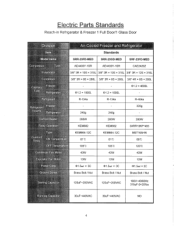
Electric Parts Standards Reach-in Refrigerator & Freezer 1 Full Door/1 Glass Door „.. 6, 0. : ,.C.-.0) I '')i,[7:L=,. [=., I I 1 ( I . 1 r, , ,, ..:Air4Cdoled.Fteezer and Refrigerator Standards SRR-23FD-MED SRR-23GD-MED SRF-23FD-MED AE4430Y-1SR AE4430Y-1SR CAE2420Z 3/8" 3R x 10S x 310L 3/8" 3R x 10S x 310L 3/8" 3R x 12S x 310L 3/8" 3R x 8S x 280L 3/8" 3R x 8S x 280L 3/8" 4R x 8S x 280L - - 01.2 x 4600L &#...
Electric Parts Standards Reach-in Refrigerator & Freezer 1 Full Door/1 Glass Door „.. 6, 0. : ,.C.-.0) I '')i,[7:L=,. [=., I I 1 ( I . 1 r, , ,, ..:Air4Cdoled.Fteezer and Refrigerator Standards SRR-23FD-MED SRR-23GD-MED SRF-23FD-MED AE4430Y-1SR AE4430Y-1SR CAE2420Z 3/8" 3R x 10S x 310L 3/8" 3R x 10S x 310L 3/8" 3R x 12S x 310L 3/8" 3R x 8S x 280L 3/8" 3R x 8S x 280L 3/8" 4R x 8S x 280L - - 01.2 x 4600L &#...
Service Manual
Page 7
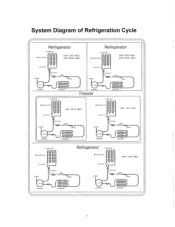
System Diagram of Refrigeration Cycle Refrigerator EVAPORATOR • WELDING POINT SRR-23FD-MED SRR-23GD-MED Refrigerator EVAPORATOR • WELDING POINT SRR-49FD-MED SRR-49GD-MED ACCUNULAT CHARGE CAPPILARY OGRE CHARGE 1/4 H.P COMPRESS CONDENSER EVAPORATOR ACCUNULAT CHARGE CAPPILARY DRYE CHARGE 1/3 H.P COMPRESS Freezer CONDENSER EVAPORATOR • WELDING POINT ACCUNULAT SRF-23FD-MED • WELDING POINT ACCUNULAT SRF-49FD-MED CHARGE CAPPILARY DRYE CHARGE CHARGE CAPPILARY DRYE CHARGE 1/2 H.P COMPRESS CONDENSER 1/2 H.P COMPRESS CONDENSER EVAPORATOR &#...
System Diagram of Refrigeration Cycle Refrigerator EVAPORATOR • WELDING POINT SRR-23FD-MED SRR-23GD-MED Refrigerator EVAPORATOR • WELDING POINT SRR-49FD-MED SRR-49GD-MED ACCUNULAT CHARGE CAPPILARY OGRE CHARGE 1/4 H.P COMPRESS CONDENSER EVAPORATOR ACCUNULAT CHARGE CAPPILARY DRYE CHARGE 1/3 H.P COMPRESS Freezer CONDENSER EVAPORATOR • WELDING POINT ACCUNULAT SRF-23FD-MED • WELDING POINT ACCUNULAT SRF-49FD-MED CHARGE CAPPILARY DRYE CHARGE CHARGE CAPPILARY DRYE CHARGE 1/2 H.P COMPRESS CONDENSER 1/2 H.P COMPRESS CONDENSER EVAPORATOR &#...

Service Manual
Page 11
... "SET.TEMP" button and then the set is same as the current temperature, the COMP. Circuit Operation Product installation Completion (Plug the power cord. ) ( Rated power source ) 1 Turn on the power switch. C (-- is displayed. A range of temperature adjustment \........R...efrigeration:+10t--3t / Freezer:+10C-23t All the compressors have 1 minute delay prior to their operation each time and they are turned in. ( When the Temperature set 1 Check the Compressor oper tion. I (Check the Display) (The current temperature is Controlled.
... "SET.TEMP" button and then the set is same as the current temperature, the COMP. Circuit Operation Product installation Completion (Plug the power cord. ) ( Rated power source ) 1 Turn on the power switch. C (-- is displayed. A range of temperature adjustment \........R...efrigeration:+10t--3t / Freezer:+10C-23t All the compressors have 1 minute delay prior to their operation each time and they are turned in. ( When the Temperature set 1 Check the Compressor oper tion. I (Check the Display) (The current temperature is Controlled.

Service Manual
Page 12
... set temperature value.running , Running off when the door is opened. It's controlled by thermal protector. Defrosting Cycle 01• Lighted on when the door is opened by the door switch. (Lighted on by switch in gla Set value "o". 1 !" Running off Running off I Keep running on at set value "o" • - 7,7503a7:',. later again after defrosting. Running off at set value "t" DRAIN HEAT, Running with compressor. --- later again after defrosting. TE K.E.. Operation time flow Cooling Cycle Lighted on when the door is opened...
... set temperature value.running , Running off when the door is opened. It's controlled by thermal protector. Defrosting Cycle 01• Lighted on when the door is opened by the door switch. (Lighted on by switch in gla Set value "o". 1 !" Running off Running off I Keep running on at set value "o" • - 7,7503a7:',. later again after defrosting. Running off at set value "t" DRAIN HEAT, Running with compressor. --- later again after defrosting. TE K.E.. Operation time flow Cooling Cycle Lighted on when the door is opened...
Service Manual
Page 14
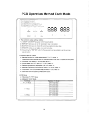
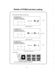
...; Displayed temperature adjustment. (-9°-+9°) value "H". • Automatic Defrosting Period Setting (every1-24 hours) value "P". • Compressor Turn ON Deviation Adjustment(0.1-2.0°) value "o". • Each value can be adjust by pressing (UP/GOWN) button, E:Press (SELECTION) button over 10 seconds for manual delrosting. D:Set desired temperature by UP&DOWN button. 3. PCB Mode A-1, A-1 Mode A-1 Mode A-2 Mode Appliation For Model SRR-72GD-MED SRR-23FD-MED SRR-49FD-MED SRR-23GD-MED SRR-49GD-MED SRF-23FD-MED SRF-49FD-MED 14 Common value of control...
...; Displayed temperature adjustment. (-9°-+9°) value "H". • Automatic Defrosting Period Setting (every1-24 hours) value "P". • Compressor Turn ON Deviation Adjustment(0.1-2.0°) value "o". • Each value can be adjust by pressing (UP/GOWN) button, E:Press (SELECTION) button over 10 seconds for manual delrosting. D:Set desired temperature by UP&DOWN button. 3. PCB Mode A-1, A-1 Mode A-1 Mode A-2 Mode Appliation For Model SRR-72GD-MED SRR-23FD-MED SRR-49FD-MED SRR-23GD-MED SRR-49GD-MED SRF-23FD-MED SRF-49FD-MED 14 Common value of control...

Service Manual
Page 15
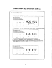
... pushing the TEMP.SET button for five seconds and the windows will be changed . [How to Set Desired Temperature] A:Press Ihe(ON/OFF) button for operation. Details of control select 1) Temperature setting • Push the TEMP.SET button and you can see the current set value with blinking red dot . [How to Set Desired Temperature] A:Press the(ON/OFF) button for operation. E:Press (SELECTION) button over 10 seconds for manual defrosting, ON/OFF...
... pushing the TEMP.SET button for five seconds and the windows will be changed . [How to Set Desired Temperature] A:Press Ihe(ON/OFF) button for operation. Details of control select 1) Temperature setting • Push the TEMP.SET button and you can see the current set value with blinking red dot . [How to Set Desired Temperature] A:Press the(ON/OFF) button for operation. E:Press (SELECTION) button over 10 seconds for manual defrosting, ON/OFF...

Service Manual
Page 16
... operation, B:Press theiTEMP.SET) button for temperature setting. E:Press (SELECTION) button over 10 seconds for manual defrosting. D:Set desired temperature by pressing (UP/DOWN) button. D:Set desired temperature by pressing (UP/DOWN) button. ON/OFF SELECTION ON;3FF TEPAP.SET UP DOWN • a Alm% •''• LI I • • gao• Aim% 0 11 11/ I U.I) LO bl inking dot ____1 B *Blinking dot shows window that can be change...
... operation, B:Press theiTEMP.SET) button for temperature setting. E:Press (SELECTION) button over 10 seconds for manual defrosting. D:Set desired temperature by pressing (UP/DOWN) button. D:Set desired temperature by pressing (UP/DOWN) button. ON/OFF SELECTION ON;3FF TEPAP.SET UP DOWN • a Alm% •''• LI I • • gao• Aim% 0 11 11/ I U.I) LO bl inking dot ____1 B *Blinking dot shows window that can be change...
Service Manual
Page 17
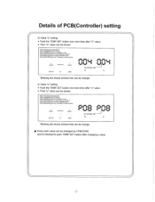
... window A or window B. 0:Sel desired temperature by pressing (UP/DOWN) button. C:Press (SELECTION) button to Set Desired Temperature] A:Press the(ON/OFF) button for operation. 8:Press the(TEMP.SET) button for manual defrosting. E:Press (SELECTION) button over 10 seconds for temperature selling. Details of PCB(Controller) setting 2) Value "o" setting • Push the TEMP.SET button one more time after changing a value. 17 ON/OFF SELECTION ON7OFF TEMP.SET UP DOWN IInesn-eI ee...
... window A or window B. 0:Sel desired temperature by pressing (UP/DOWN) button. C:Press (SELECTION) button to Set Desired Temperature] A:Press the(ON/OFF) button for operation. 8:Press the(TEMP.SET) button for manual defrosting. E:Press (SELECTION) button over 10 seconds for temperature selling. Details of PCB(Controller) setting 2) Value "o" setting • Push the TEMP.SET button one more time after changing a value. 17 ON/OFF SELECTION ON7OFF TEMP.SET UP DOWN IInesn-eI ee...
Service Manual
Page 18
... temperature mode is set with rebooting controller(lt wouldn't be changed .). [How to select window A or window B. 1):Set desired temperature by UP&DOWN button. • Finally you can change that by pressing (UP/DOWN) button. E:Press (SELECTION) button over 10 seconds for manual defrosting. B:Press the(TEMP,SET) bulton for manual defrosting, ON/O▪ FF SELECTION ON/OFF 4ININ $ L AMP IMP. D:Sel desired temperature by pressing (UP/DOWN) button. r 1L TEMP.SET...
... temperature mode is set with rebooting controller(lt wouldn't be changed .). [How to select window A or window B. 1):Set desired temperature by UP&DOWN button. • Finally you can change that by pressing (UP/DOWN) button. E:Press (SELECTION) button over 10 seconds for manual defrosting. B:Press the(TEMP,SET) bulton for manual defrosting, ON/O▪ FF SELECTION ON/OFF 4ININ $ L AMP IMP. D:Sel desired temperature by pressing (UP/DOWN) button. r 1L TEMP.SET...
Service Manual
Page 20
... manual defrosting. ON/OFF SELECTION ON/OFF I!' .4. , . 4IR, .4 h i-1 4nr , ea , %MP TEMP.SET DOWN < 2door freezer unit > [How to select window A or window B. D:Sel desired temperature by pressing (UP/DOWN) button. C:Press (SELECTION) button to Set Desired Temperature] A:Press the(ON/OFF) button for operation. Alarm switch < 1door cooler, freezer unit > MEM. 411111111 4IMMINO 4I 110, 1111/1111 aMM. Details of PCB(Controller) setting 4 Every type of the "Mode...
... manual defrosting. ON/OFF SELECTION ON/OFF I!' .4. , . 4IR, .4 h i-1 4nr , ea , %MP TEMP.SET DOWN < 2door freezer unit > [How to select window A or window B. D:Sel desired temperature by pressing (UP/DOWN) button. C:Press (SELECTION) button to Set Desired Temperature] A:Press the(ON/OFF) button for operation. Alarm switch < 1door cooler, freezer unit > MEM. 411111111 4IMMINO 4I 110, 1111/1111 aMM. Details of PCB(Controller) setting 4 Every type of the "Mode...
Service Manual
Page 21
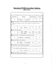
...EVAP. H -9 degrees - 9 degrees 0 0 •Displayed temperature adjustment. 0 0.1 degree - 2.0 degrees 0.3 0.3 • Compressor Turn ON Deviation Adjustmen -The cooling system will be operated when the inside cabinet temperature nnRR up "o" value from setting Temp. p I 1 hour - 24 hours 12 3 • Automatic Defrosting Period Setting 21 coil temperature setting for defrosting. Standard PCB(Controller) Setting MED Product Direction Range Refrigerator Freezer A 00 degree - 15 degrees 6 6 • Alarming tunction. It you set b degrees, you will be warned when...
...EVAP. H -9 degrees - 9 degrees 0 0 •Displayed temperature adjustment. 0 0.1 degree - 2.0 degrees 0.3 0.3 • Compressor Turn ON Deviation Adjustmen -The cooling system will be operated when the inside cabinet temperature nnRR up "o" value from setting Temp. p I 1 hour - 24 hours 12 3 • Automatic Defrosting Period Setting 21 coil temperature setting for defrosting. Standard PCB(Controller) Setting MED Product Direction Range Refrigerator Freezer A 00 degree - 15 degrees 6 6 • Alarming tunction. It you set b degrees, you will be warned when...
Service Manual
Page 22
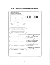
... Operation Method Each Mode [How to select window A or window B. E:Press (SELECTION) button over 10 seconds for five) seconds. ONYOFF SELECTION ON/OFF / 41.1 04.1.1 1 11®11 1 4111. •4111/0 / /I / 1®l i®11®1 I TEMP. SET UP DOWN Turn on PCB controller. )Will be continued 22 C Will be displayed "FFF" on the power switch Press adjustment switch(Temp.set ) for one time. O' Press adjustment switch(Temp.set...
... Operation Method Each Mode [How to select window A or window B. E:Press (SELECTION) button over 10 seconds for five) seconds. ONYOFF SELECTION ON/OFF / 41.1 04.1.1 1 11®11 1 4111. •4111/0 / /I / 1®l i®11®1 I TEMP. SET UP DOWN Turn on PCB controller. )Will be continued 22 C Will be displayed "FFF" on the power switch Press adjustment switch(Temp.set ) for one time. O' Press adjustment switch(Temp.set...

Service Manual
Page 23
... displayed "000" on PCB controller. ► Press adjustment switch(Temo.set) for one time. Will be displayed "POO" on PCB controller. C Will be displayed "FFF" on PCB controller. 1 Will be displayed "CCC" on PCB controller. PCB Operation Method Each Mode C Will be displayed "HOO" on PCB controller. Press "UP" or "DOWN" button decrease degrees or increase degrees ► Press adjustment switch(Temo.set ) for one time. Will be changed current temperature...
... displayed "000" on PCB controller. ► Press adjustment switch(Temo.set) for one time. Will be displayed "POO" on PCB controller. C Will be displayed "FFF" on PCB controller. 1 Will be displayed "CCC" on PCB controller. PCB Operation Method Each Mode C Will be displayed "HOO" on PCB controller. Press "UP" or "DOWN" button decrease degrees or increase degrees ► Press adjustment switch(Temo.set ) for one time. Will be changed current temperature...
Service Manual
Page 25
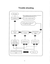
... fan motor. The capillary tube Clogged. fan motor I< The controller has to be shown when the EVAP. Trouble shooting No cooling Any message on the controller(OP,SH) 0 #SH error masage can be checked if the terminal block has electric power. 14/ No power Replace one ) 25 Coil temperature or cabinet tempreature goes down under -35 degrees C. Compressor is working in the cabinet. 4, Any failure on the Compressor or Running...
... fan motor. The capillary tube Clogged. fan motor I< The controller has to be shown when the EVAP. Trouble shooting No cooling Any message on the controller(OP,SH) 0 #SH error masage can be checked if the terminal block has electric power. 14/ No power Replace one ) 25 Coil temperature or cabinet tempreature goes down under -35 degrees C. Compressor is working in the cabinet. 4, Any failure on the Compressor or Running...
Service Manual
Page 26
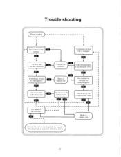
... condenser fan motor Repair or replace one Ambient temperature is blocked by manual defrosting & adjust automatic defrosting period Any failure on the controller. The door was opened repeatedly El Any leakage around the door gasket. Too much frost on the Evap. r CRemove the frost on the Evap. Coil. Trouble shooting ( Poor cooling Air flow is too high(over 35t). • Any problem to ventilate the condensing unit. V Condenser coil & air filter...
... condenser fan motor Repair or replace one Ambient temperature is blocked by manual defrosting & adjust automatic defrosting period Any failure on the controller. The door was opened repeatedly El Any leakage around the door gasket. Too much frost on the Evap. r CRemove the frost on the Evap. Coil. Trouble shooting ( Poor cooling Air flow is too high(over 35t). • Any problem to ventilate the condensing unit. V Condenser coil & air filter...
Service Manual
Page 27
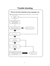
Frost on PCB. The controller has to be checked if the defrost heater terminal block has electric power. Replace the one ) 27 Trouble shooting There is any frost remaining on the evaporator coil. • The dfrost function is - Coil Manual defrost operation. (Push the SELECTION button for 10 sec.) V F Manual defrost operation displayed. (flashing "d00") • Replace the control ler) Defrosting activated. is maintained by the common value "t", "d" & "p" on Evap. Any failure on defrost heater. Coil sensor Any failure on Evap.
Frost on PCB. The controller has to be checked if the defrost heater terminal block has electric power. Replace the one ) 27 Trouble shooting There is any frost remaining on the evaporator coil. • The dfrost function is - Coil Manual defrost operation. (Push the SELECTION button for 10 sec.) V F Manual defrost operation displayed. (flashing "d00") • Replace the control ler) Defrosting activated. is maintained by the common value "t", "d" & "p" on Evap. Any failure on defrost heater. Coil sensor Any failure on Evap.
Service Manual
Page 28
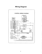
VOlt OEN BMX T YELLOW f- e,LA •c) TELL,. TERMINAL BLOCK , 1 401 2 3 N 5 8 WM ;TT 164101, *WE WIFE oo KA Igyf • ITE PRE EM ,WE 28 Wiring Diagram 7 CONTROL WIRING DIAGRAM CP-ACENHEI FAM ii0T-BWASW) GPE-44 I MODE:(A-1) SRR-23fD-MED T€PIMI14AL BLOCK 1 COMP I 2 COMP 2 1 COMP 3 4 11F HEATER 1 5 0,F HEATER 2 6 O.F HEATER 3 7 EAVP P ,2 8 EAVP FAN 3 MAIN HEAT 1,2 ID Of HEAT 3 11 MOP HEAT 1 12 OCOR HEAT 2 BL 1i COM 2 5 COM Fi(SSOR 3EfFOST i3ECER 128.YR) 04AtkAlfliCs 111-ITE a. ,SEA&CIR HAFIES3 BM MAW -
VOlt OEN BMX T YELLOW f- e,LA •c) TELL,. TERMINAL BLOCK , 1 401 2 3 N 5 8 WM ;TT 164101, *WE WIFE oo KA Igyf • ITE PRE EM ,WE 28 Wiring Diagram 7 CONTROL WIRING DIAGRAM CP-ACENHEI FAM ii0T-BWASW) GPE-44 I MODE:(A-1) SRR-23fD-MED T€PIMI14AL BLOCK 1 COMP I 2 COMP 2 1 COMP 3 4 11F HEATER 1 5 0,F HEATER 2 6 O.F HEATER 3 7 EAVP P ,2 8 EAVP FAN 3 MAIN HEAT 1,2 ID Of HEAT 3 11 MOP HEAT 1 12 OCOR HEAT 2 BL 1i COM 2 5 COM Fi(SSOR 3EfFOST i3ECER 128.YR) 04AtkAlfliCs 111-ITE a. ,SEA&CIR HAFIES3 BM MAW -


