
Quick Start Guide
Page 1
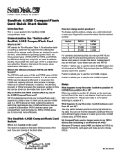
... FAT32 formats affect my use the whole 4.0GB of the 4.0GB CompactFlash card? My CompactFlash card no longer works in position #1. Windows XP formats cards 64MB and higher as FAT32 by Microsoft to address clusters. Position #3 = 2.0GB Position #2 = 2.0GB Position #1 = 4.0GB 80-36-00312 SanDisk 4.0GB CompactFlash Card Quick Start Guide Introduction This is a user guide for File Allocation Table. Even if the data is...
... FAT32 formats affect my use the whole 4.0GB of the 4.0GB CompactFlash card? My CompactFlash card no longer works in position #1. Windows XP formats cards 64MB and higher as FAT32 by Microsoft to address clusters. Position #3 = 2.0GB Position #2 = 2.0GB Position #1 = 4.0GB 80-36-00312 SanDisk 4.0GB CompactFlash Card Quick Start Guide Introduction This is a user guide for File Allocation Table. Even if the data is...

Product Manual
Page 7
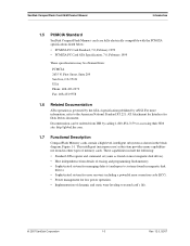
... 1.1 General Description SanDisk CompactFlash® Memory Card products provide high capacity solid-state flash memory that electrically complies with the Personal Computer Memory Card International Association ATA (PC Card ATA) standard. (In Japan, the applicable standards group is JEIDA.) The CompactFlash Memory Card Series also supports a True IDE Mode that is protected by a powerful Error Correcting Code (ECC). Each sector is electrically compatible with a Type II PCMCIA adapter...
... 1.1 General Description SanDisk CompactFlash® Memory Card products provide high capacity solid-state flash memory that electrically complies with the Personal Computer Memory Card International Association ATA (PC Card ATA) standard. (In Japan, the applicable standards group is JEIDA.) The CompactFlash Memory Card Series also supports a True IDE Mode that is protected by a powerful Error Correcting Code (ECC). Each sector is electrically compatible with a Type II PCMCIA adapter...

Product Manual
Page 8
... SanDisk CompactFlash Card OEM Product Manual 1.2 Features SanDisk CompactFlash Memory cards provide the following system features: • Up to 16 GB of mass storage data • PC Card ATA protocol compatible • True IDE Mode compatible • Very low CMOS power • Very high performance • Very rugged • Low weight • Noiseless • Low Profile • +5 Volts or +3.3 Volts operation • Automatic error...
... SanDisk CompactFlash Card OEM Product Manual 1.2 Features SanDisk CompactFlash Memory cards provide the following system features: • Up to 16 GB of mass storage data • PC Card ATA protocol compatible • True IDE Mode compatible • Very low CMOS power • Very high performance • Very rugged • Low weight • Noiseless • Low Profile • +5 Volts or +3.3 Volts operation • Automatic error...
Product Manual
Page 9
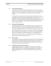
... capabilities not found in magnetic disk drives). • Sophisticated system for error recovery including a powerful error correction code (ECC). • Power management for Disk Drives document. SanDisk CompactFlash Card OEM Product Manual Introduction 1.5 PCMCIA Standard SanDisk CompactFlash Memory cards are fully electrically compatible with the PCMCIA specifications listed below: • PCMCIA PC Card Standard, 7.0, February 1999 • PCMCIA PC Card ATA Specification, 7.0, February 1999 These specifications may be ordered from...
... capabilities not found in magnetic disk drives). • Sophisticated system for error recovery including a powerful error correction code (ECC). • Power management for Disk Drives document. SanDisk CompactFlash Card OEM Product Manual Introduction 1.5 PCMCIA Standard SanDisk CompactFlash Memory cards are fully electrically compatible with the PCMCIA specifications listed below: • PCMCIA PC Card Standard, 7.0, February 1999 • PCMCIA PC Card ATA Specification, 7.0, February 1999 These specifications may be ordered from...
Product Manual
Page 10
... maximize flash life expectancy. 1.7.4 Using Erase Sector and Write Commands SanDisk CompactFlash Memory cards support the CF ERASE SECTOR and WRITE WITHOUT ERASE commands. The CompactFlash Memory Card soft error rate specification is completely transparent to the host and does not consume any user data space. In some applications, write operations may be able to access future SanDisk cards built with new flash technology without having to update...
... maximize flash life expectancy. 1.7.4 Using Erase Sector and Write Commands SanDisk CompactFlash Memory cards support the CF ERASE SECTOR and WRITE WITHOUT ERASE commands. The CompactFlash Memory Card soft error rate specification is completely transparent to the host and does not consume any user data space. In some applications, write operations may be able to access future SanDisk cards built with new flash technology without having to update...

Product Manual
Page 14
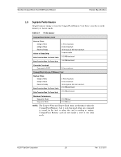
Product Specifications SanDisk CompactFlash Card OEM Product Manual Sleep mode currently is specified under the condition that all card inputs are static CMOS levels and in a "Not Busy" operating state. ripple (p-p) 3.3V +/- 5% Memory Subsystema CompactFlash Memory Card Sleep Up to 512 MB 300 µ 1.0 GB 600 µ Over 1.0 GB 1 mA Read 50 mA Write 65 mA Read/Write Peak 100 mA Memory Subsystema CompactFlash Extreme III Memory Card... 100 mA 100 mA 02/07, Rev. 12.0 2-2 © 2007 SanDisk Corporation Table 2-2 Power Requirements DC Input Voltage (Vcc) 100 mV max.
Product Specifications SanDisk CompactFlash Card OEM Product Manual Sleep mode currently is specified under the condition that all card inputs are static CMOS levels and in a "Not Busy" operating state. ripple (p-p) 3.3V +/- 5% Memory Subsystema CompactFlash Memory Card Sleep Up to 512 MB 300 µ 1.0 GB 600 µ Over 1.0 GB 1 mA Read 50 mA Write 65 mA Read/Write Peak 100 mA Memory Subsystema CompactFlash Extreme III Memory Card... 100 mA 100 mA 02/07, Rev. 12.0 2-2 © 2007 SanDisk Corporation Table 2-2 Power Requirements DC Input Voltage (Vcc) 100 mV max.
Product Manual
Page 15
SanDisk CompactFlash Card OEM Product Manual Product Specifications 2.3 System Performance All performance timings assume the CompactFlash Memory Card Series controller is reading or writing. Table 2-3 Performance CompactFlash Memory Card Start-up Times Sleep to Write Sleep to Read Reset to Ready Active to Sleep Delay Data Transfer Rate To/From Flash Data... Controller Overhead Command to DRQ 50 ms maximum CompactFlash Extreme III Memory Card Start-up Times Sleep to Write Sleep to Read Reset to Ready Data Transfer Rate To/From Flash Data Transfer Rate To/From Host 2.5 ms maximum 20...
SanDisk CompactFlash Card OEM Product Manual Product Specifications 2.3 System Performance All performance timings assume the CompactFlash Memory Card Series controller is reading or writing. Table 2-3 Performance CompactFlash Memory Card Start-up Times Sleep to Write Sleep to Read Reset to Ready Active to Sleep Delay Data Transfer Rate To/From Flash Data... Controller Overhead Command to DRQ 50 ms maximum CompactFlash Extreme III Memory Card Start-up Times Sleep to Write Sleep to Read Reset to Ready Data Transfer Rate To/From Flash Data Transfer Rate To/From Host 2.5 ms maximum 20...
Product Manual
Page 19
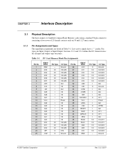
... active signals have a "-" prefix. Pin types are listed in Table 3-1. I O I O O I I/O I/O I/O I/O I O - Table 3-1 PC Card Memory Mode Pin Assignments Pin No. 1 2 3 4 5 6 7 8 9 10 11 12 13 14 15 16 17 18 19 20 21 22 23 24 ...RESET -WAIT -INPACK -REG BVD2 BVD1 D08 D09 D10 GND Pin Type O I/O I/O I/O I/O I/O I O I I I /O - CHAPTER 3 Interface Description 3.1 Physical Description The host connects to SanDisk CompactFlash Memory cards using a standard 50-pin connector consisting of two rows of 25 female contacts each on 50 mil (1.27 mm) centers. 3.1.1 Pin Assignments and Types The signal...
... active signals have a "-" prefix. Pin types are listed in Table 3-1. I O I O O I I/O I/O I/O I/O I O - Table 3-1 PC Card Memory Mode Pin Assignments Pin No. 1 2 3 4 5 6 7 8 9 10 11 12 13 14 15 16 17 18 19 20 21 22 23 24 ...RESET -WAIT -INPACK -REG BVD2 BVD1 D08 D09 D10 GND Pin Type O I/O I/O I/O I/O I/O I O I I I /O - CHAPTER 3 Interface Description 3.1 Physical Description The host connects to SanDisk CompactFlash Memory cards using a standard 50-pin connector consisting of two rows of 25 female contacts each on 50 mil (1.27 mm) centers. 3.1.1 Pin Assignments and Types The signal...
Product Manual
Page 22
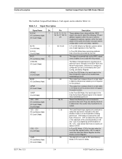
... the host to determine if the card is configured. Interface Description SanDisk CompactFlash Card OEM Product Manual The SanDisk CompactFlash Memory Card signals are used to select the following: I/O port address registers within the card, memorymapped port address registers within the card, a byte in the card's information structure and its socket. -CE1, -CE2 I (PC Card Memory Mode) (PC Card I/O Mode) 7, 32 The Card Enable input signals are connected...
... the host to determine if the card is configured. Interface Description SanDisk CompactFlash Card OEM Product Manual The SanDisk CompactFlash Memory Card signals are used to select the following: I/O port address registers within the card, memorymapped port address registers within the card, a byte in the card's information structure and its socket. -CE1, -CE2 I (PC Card Memory Mode) (PC Card I/O Mode) 7, 32 The Card Enable input signals are connected...
Product Manual
Page 24
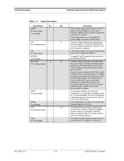
... O 37 (PC Card Memory Mode) -IREQ (PC Card I/O Mode) INTRQ (True IDE Mode) -REG I 44 (PC Card Memory Mode) -REG (PC Card I/O Mode) Description The I/O write strobe pulse is used to the host. No access of the signal (trailing edge). The host memory card socket must also be grounded by the host interface. Interface Description SanDisk CompactFlash Card OEM Product Manual Table 3-4 Signal Description...
... O 37 (PC Card Memory Mode) -IREQ (PC Card I/O Mode) INTRQ (True IDE Mode) -REG I 44 (PC Card Memory Mode) -REG (PC Card I/O Mode) Description The I/O write strobe pulse is used to the host. No access of the signal (trailing edge). The host memory card socket must also be grounded by the host interface. Interface Description SanDisk CompactFlash Card OEM Product Manual Table 3-4 Signal Description...
Product Manual
Page 25
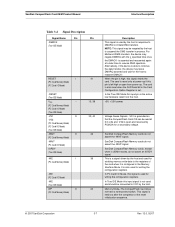
SanDisk CompactFlash Card OEM Product Manual Interface Description Table 3-4 Signal Description Signal Name Dir. When the pin is high, this signal is used for strobing memory write data to the registers of the reset initialization sequence. © 2007 SanDisk Corporation 3-7 Rev. 12.0, 02/07 The card is reset ... by the host in process. Alternatively, if the device is used by the host and used for the host to resume DMA operation. SanDisk CompactFlash Memory cards do not assert the -WAIT signal. This is asserted and reasserted again at 3.3 volts and VS2 is set.
SanDisk CompactFlash Card OEM Product Manual Interface Description Table 3-4 Signal Description Signal Name Dir. When the pin is high, this signal is used for strobing memory write data to the registers of the reset initialization sequence. © 2007 SanDisk Corporation 3-7 Rev. 12.0, 02/07 The card is reset ... by the host in process. Alternatively, if the device is used by the host and used for the host to resume DMA operation. SanDisk CompactFlash Memory cards do not assert the -WAIT signal. This is asserted and reasserted again at 3.3 volts and VS2 is set.

Product Manual
Page 26
... expecting a word data transfer cycle. 3.3 Electrical Specification All D.C. Interface Description SanDisk CompactFlash Card OEM Product Manual Table 3-4 Signal Description Signal Name Dir. Pin -IOIS16 (PC Card I/O Mode) -IOCS16 (True IDE Mode) Description I/O Operation-When the card is configured for I /O Selected is intentionally higher in Table 3-6. This output signal is asserted low when this device is used for the CompactFlash Memory Card Series are...
... expecting a word data transfer cycle. 3.3 Electrical Specification All D.C. Interface Description SanDisk CompactFlash Card OEM Product Manual Table 3-4 Signal Description Signal Name Dir. Pin -IOIS16 (PC Card I/O Mode) -IOCS16 (True IDE Mode) Description I/O Operation-When the card is configured for I /O Selected is intentionally higher in Table 3-6. This output signal is asserted low when this device is used for the CompactFlash Memory Card Series are...

Product Manual
Page 29
...; 2007 SanDisk Corporation 3-11 Rev. 12.0, 02/07 Skews and delays from the system driver/receiver to the card must be accounted for all types of memory. Table 3-10 Common Memory Read Timing Specification Speed Version Item Read Cycle Time Address Access Timea Card Enable Access... Enable Time from -OE Data Valid from system RESET VCC -CE1, -CE2 Supplied by the system. NOTE: All timings measured at the CompactFlash Memory Card. SanDisk CompactFlash Card OEM Product Manual Interface Description Figure 3-2 Power Up/Power Down Timing for Systems not supporting RESET tpr VCC Min.
...; 2007 SanDisk Corporation 3-11 Rev. 12.0, 02/07 Skews and delays from the system driver/receiver to the card must be accounted for all types of memory. Table 3-10 Common Memory Read Timing Specification Speed Version Item Read Cycle Time Address Access Timea Card Enable Access... Enable Time from -OE Data Valid from system RESET VCC -CE1, -CE2 Supplied by the system. NOTE: All timings measured at the CompactFlash Memory Card. SanDisk CompactFlash Card OEM Product Manual Interface Description Figure 3-2 Power Up/Power Down Timing for Systems not supporting RESET tpr VCC Min.

Product Manual
Page 49
CE1- A0 0 1 X 0 0 X Offset 1 Dh Data Bus D15-D0 D15-D0 4.5.2 Error Register (Address-1F1[171]; D2 ABRT Set if the command has been aborted because of the Logical Block Address (LBA) for any CompactFlash Memory Card data access for the subsequent command. © 2007 SanDisk Corporation 4-5 Rev. 12.0, 02/07 D1 0 Bit set to 0. Offset 1, 0Dh Write Only) This register...
CE1- A0 0 1 X 0 0 X Offset 1 Dh Data Bus D15-D0 D15-D0 4.5.2 Error Register (Address-1F1[171]; D2 ABRT Set if the command has been aborted because of the Logical Block Address (LBA) for any CompactFlash Memory Card data access for the subsequent command. © 2007 SanDisk Corporation 4-5 Rev. 12.0, 02/07 D1 0 Bit set to 0. Offset 1, 0Dh Write Only) This register...

Product Manual
Page 51
SanDisk CompactFlash Card OEM Product Manual ATA Register Set and Protocol 4.5.9 Status & Alternate Status Registers (Address-1F7[177]&3F6[376]; No other bits in this register are valid when this bit is set to 0. D1 0 Always set...DSC Set when the card is capable of performing card operations. D2 CORR Set when a correctable data error has been encountered and the data has...card status when read operation. This bit is cleared at power-up and remains cleared until card is ready to the command buffer and registers and the host is used to control the CompactFlash Memory Card...
SanDisk CompactFlash Card OEM Product Manual ATA Register Set and Protocol 4.5.9 Status & Alternate Status Registers (Address-1F7[177]&3F6[376]; No other bits in this register are valid when this bit is set to 0. D1 0 Always set...DSC Set when the card is capable of performing card operations. D2 CORR Set when a correctable data error has been encountered and the data has...card status when read operation. This bit is cleared at power-up and remains cleared until card is ready to the command buffer and registers and the host is used to control the CompactFlash Memory Card...

Product Manual
Page 64
... values in nanoseconds, the minimum cycle time the card supports while performing data transfers using flow control. Words 85, 86, and 87 indicates features/ command sets enabled. Words 82-84: Features/Command Sets Supported. Bit 14 of Word 83 and Word 84 will be set not supported 11 --- ATA Command Description SanDisk CompactFlash Card OEM Product Manual Word 68: Minimum PIO Transfer Cycle Time...
... values in nanoseconds, the minimum cycle time the card supports while performing data transfers using flow control. Words 85, 86, and 87 indicates features/ command sets enabled. Words 82-84: Features/Command Sets Supported. Bit 14 of Word 83 and Word 84 will be set not supported 11 --- ATA Command Description SanDisk CompactFlash Card OEM Product Manual Word 68: Minimum PIO Transfer Cycle Time...
Product Manual
Page 65
... Security Set Password command 2 0 Removable Media feature set not supported 3 1 Power Management feature set supported 4 0 Packet Command feature set not enabled 5 1 Write cache enabled 6 1 Look-ahead enabled 7 0 Release Interrupt not enabled 8 0 Service Interrupt not enabled 9 0 Device Reset command not supported 10 0 Host Protected Area feature set to provide indication that describe support and selection of word 87 are reserved. SanDisk CompactFlash Card OEM Product Manual ATA...
... Security Set Password command 2 0 Removable Media feature set not supported 3 1 Power Management feature set supported 4 0 Packet Command feature set not enabled 5 1 Write cache enabled 6 1 Look-ahead enabled 7 0 Release Interrupt not enabled 8 0 Service Interrupt not enabled 9 0 Device Reset command not supported 10 0 Host Protected Area feature set to provide indication that describe support and selection of word 87 are reserved. SanDisk CompactFlash Card OEM Product Manual ATA...

Product Manual
Page 70
..., the Command Block registers contain the cylinder, head and sector number of the last sector read terminates at the start of the data block, not on a Read Sector(s) Command. The transfer begins at the beginning of the block or partial block transfer, but on... except that the number of sectors defined by the Set Multiple Mode command, which contains the number of sectors defined by a final, partial block transfer. If an error occurs, the read . ATA Command Description SanDisk CompactFlash Card OEM Product Manual 5.1.11 Read Multiple-C4H The Read Multiple command performs...
..., the Command Block registers contain the cylinder, head and sector number of the last sector read terminates at the start of the data block, not on a Read Sector(s) Command. The transfer begins at the beginning of the block or partial block transfer, but on... except that the number of sectors defined by the Set Multiple Mode command, which contains the number of sectors defined by a final, partial block transfer. If an error occurs, the read . ATA Command Description SanDisk CompactFlash Card OEM Product Manual 5.1.11 Read Multiple-C4H The Read Multiple command performs...
Product Manual
Page 73
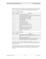
... Uncorrectable ECC error Corrected ECC error Self test or diagnostic failed ID not found Spare sectors exhausted Data transfer error/aborted command Corrupted media format Write/erase failed 5.1.17 Seek-7XH This command is effectively a NOP command to the card although it ... Error Register. SanDisk CompactFlash Card OEM Product Manual ATA Command Description Table 5-24 defines the valid extended error codes for the CompactFlash Memory Card Series product. The extended error code is out of cylinder and head or LBA address and returns an error if the address is returned to the card...
... Uncorrectable ECC error Corrected ECC error Self test or diagnostic failed ID not found Spare sectors exhausted Data transfer error/aborted command Corrupted media format Write/erase failed 5.1.17 Seek-7XH This command is effectively a NOP command to the card although it ... Error Register. SanDisk CompactFlash Card OEM Product Manual ATA Command Description Table 5-24 defines the valid extended error codes for the CompactFlash Memory Card Series product. The extended error code is out of cylinder and head or LBA address and returns an error if the address is returned to the card...

Product Manual
Page 74
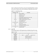
... command is issued, all features that are supported. The 9AH feature is unique to CompactFlash Memory cards and are used by the host to enable and clear 8-bit data transfer mode. ATA Command Description SanDisk CompactFlash Card OEM Product Manual 5.1.18 Set Features-EFH This command is used to establish or select certain features. Table 5-26 Set Features Bit 7 6 5 4 3 2 1 0 Command (7) EFH C/D/H (6) X Drive X Cyl High...
... command is issued, all features that are supported. The 9AH feature is unique to CompactFlash Memory cards and are used by the host to enable and clear 8-bit data transfer mode. ATA Command Description SanDisk CompactFlash Card OEM Product Manual 5.1.18 Set Features-EFH This command is used to establish or select certain features. Table 5-26 Set Features Bit 7 6 5 4 3 2 1 0 Command (7) EFH C/D/H (6) X Drive X Cyl High...


