

Service Manual
Page 18
... Instructions 5-3-1. Loosen a screw this six point form Rear. 1. Be careful the hook. (Red) 2. Remove 2 screw caps. 2. Open the Key connector. (Violet) 1. Open the LCD connector. (Blue) 5-4 SAMSUNG Proprietary-Contents may change without notice This Document can not be used without Samsung's authorization Open 2 covers. (Blue) 3. Exploded View/Disassembly&Assembly Instructions 5-3. Disassembly 1 2 1. Make the...
... Instructions 5-3-1. Loosen a screw this six point form Rear. 1. Be careful the hook. (Red) 2. Remove 2 screw caps. 2. Open the Key connector. (Violet) 1. Open the LCD connector. (Blue) 5-4 SAMSUNG Proprietary-Contents may change without notice This Document can not be used without Samsung's authorization Open 2 covers. (Blue) 3. Exploded View/Disassembly&Assembly Instructions 5-3. Disassembly 1 2 1. Make the...

Service Manual
Page 21
...Red) accoding to main window and put insulation tape on connector. (Blue) 4. And put the speaker and motor module. 1. And put the sub PBA considering sub hook(blue circle). 3 4 Verify White silk line ※ Folding position 1. At first attach LCD to picture. 3. And put insulation tape on connector. 5-7 SAMSUNG... Proprietary-Contents may change without notice This Document can not be used without Samsung's authorization And combined camera connector to sub-PBA 2. 5-3-2. Assembly 1 Exploded...
...Red) accoding to main window and put insulation tape on connector. (Blue) 4. And put the speaker and motor module. 1. And put the sub PBA considering sub hook(blue circle). 3 4 Verify White silk line ※ Folding position 1. At first attach LCD to picture. 3. And put insulation tape on connector. 5-7 SAMSUNG... Proprietary-Contents may change without notice This Document can not be used without Samsung's authorization And combined camera connector to sub-PBA 2. 5-3-2. Assembly 1 Exploded...
Service Manual
Page 23
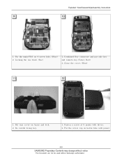
Locking the one hook. (Rec) 1. Combined Key connector and put side key and camera key.(Violet, Red) 2. Be careful losing key. 1. Close the cover. (Blue) 11 12 1. Put rear cover on 4 screw hole. (Blue) 2. Put the main-PBA on Assay and lock. 2. Put the screw cap on below hole with driver. 2. Exploded View/Disassembly&Assembly Instructions 9 10 1. Fasten a screw at 6 points with pinset 5-9 SAMSUNG Proprietary-Contents may change without notice This Document can not be used without Samsung's authorization
Locking the one hook. (Rec) 1. Combined Key connector and put side key and camera key.(Violet, Red) 2. Be careful losing key. 1. Close the cover. (Blue) 11 12 1. Put rear cover on 4 screw hole. (Blue) 2. Put the main-PBA on Assay and lock. 2. Put the screw cap on below hole with driver. 2. Exploded View/Disassembly&Assembly Instructions 9 10 1. Fasten a screw at 6 points with pinset 5-9 SAMSUNG Proprietary-Contents may change without notice This Document can not be used without Samsung's authorization


