
User Manual
Page 1
High Resolution D/N IR Dome Camera User Manual SCD-2020R
High Resolution D/N IR Dome Camera User Manual SCD-2020R

User Manual
Page 2
... period is the registered trademark of this product is 3 years. B T ■ ■ High Resolution D/N IR Dome Camera User Manual Copyright ©2010 Samsung Techwin Co., Ltd. However, the followings are the registered trademark of this document. Trademark is the registered logo of time Under... no formal guarantee shall be entirely on the user's own responsibility. Samsung Techwin reserves the right to the system operation. • Deteriorated performance or natural worn-out in this document, but no ...
... period is the registered trademark of this product is 3 years. B T ■ ■ High Resolution D/N IR Dome Camera User Manual Copyright ©2010 Samsung Techwin Co., Ltd. However, the followings are the registered trademark of this document. Trademark is the registered logo of time Under... no formal guarantee shall be entirely on the user's own responsibility. Samsung Techwin reserves the right to the system operation. • Deteriorated performance or natural worn-out in this document, but no ...

User Manual
Page 3
To help you understand this manual thoroughly, we'll introduce our model description. ■ SCD-2020R SERIES • NTSC MODEL SCD-2020RN • PAL MODEL SCD-2020RP ■ MODEL DESCRIPTION • SCD-2020RX_ SIGNAL SYSTEM • SIGNAL SYSTEM N ˧ NTSC MODEL P ˧ PAL MODEL Before operating the camera, confirm the camera model and correct input power voltage.
To help you understand this manual thoroughly, we'll introduce our model description. ■ SCD-2020R SERIES • NTSC MODEL SCD-2020RN • PAL MODEL SCD-2020RP ■ MODEL DESCRIPTION • SCD-2020RX_ SIGNAL SYSTEM • SIGNAL SYSTEM N ˧ NTSC MODEL P ˧ PAL MODEL Before operating the camera, confirm the camera model and correct input power voltage.

User Manual
Page 4
... 8 fire. 5. C WARNING 1 • To prevent damage which may result in the literature accompanying the appliance. Do not connect multiple cameras to the presence 1 of camera may cause 7 abnormal heat generation or fire. 4. DO NOT OPEN 7 CAUTION: TO REDUCE THE RISK OF ELECTRIC SHOCK, DO NOT REMOVE... SERVICING TO QUALIFIED SERVICE PERSONNEL. 9 This symbol indicates that is intended to alert the user to a single adapter. When installing the camera, fasten it securely and firmly. safety information 6 CAUTION RISK OF ELECTRIC SHOCK.
... 8 fire. 5. C WARNING 1 • To prevent damage which may result in the literature accompanying the appliance. Do not connect multiple cameras to the presence 1 of camera may cause 7 abnormal heat generation or fire. 4. DO NOT OPEN 7 CAUTION: TO REDUCE THE RISK OF ELECTRIC SHOCK, DO NOT REMOVE... SERVICING TO QUALIFIED SERVICE PERSONNEL. 9 This symbol indicates that is intended to alert the user to a single adapter. When installing the camera, fasten it securely and firmly. safety information 6 CAUTION RISK OF ELECTRIC SHOCK.

User Manual
Page 5
...;C), low temperature (below -10°C), or high humidity. Doing so may cause fire or electric shock. 9. Keep out of the camera. English_5 screwdrivers, coins, metal parts, etc.) or containers filled with good ventilation. 7. doing so may damage the CCD image sensor.... subject to fire, electric shock, or falling objects. 7. Avoid aiming the camera directly towards extremely bright objects such as sun, as a disconnect device and shall stay readily operable at any way. (samsung is a lightning. ● SAFETY INFORMATION 6. Do not install the unit in a...
...;C), low temperature (below -10°C), or high humidity. Doing so may cause fire or electric shock. 9. Keep out of the camera. English_5 screwdrivers, coins, metal parts, etc.) or containers filled with good ventilation. 7. doing so may damage the CCD image sensor.... subject to fire, electric shock, or falling objects. 7. Avoid aiming the camera directly towards extremely bright objects such as sun, as a disconnect device and shall stay readily operable at any way. (samsung is a lightning. ● SAFETY INFORMATION 6. Do not install the unit in a...

User Manual
Page 9
... Function The intensity of the IR-LEDs automatically adjust depending upon the closeness of 600 TV lines for color and 700 TV lines for any camera movement, to provide clear images even in dark environments. PAL : English, French, German, Spanish, Italian, Chinese, Russian, Polish, Czech, ...contrast to the appropriate mode, depending on the monitor. y DIS (Digital Image Stabilizer) The DIS function compensates for BW y SSNR3 (Samsung Super Noise Reduction) Function The high-performance W-V DSP chip effectively removes low-light gain noise and afterimage to produce more balanced image ...
... Function The intensity of the IR-LEDs automatically adjust depending upon the closeness of 600 TV lines for color and 700 TV lines for any camera movement, to provide clear images even in dark environments. PAL : English, French, German, Spanish, Italian, Chinese, Russian, Polish, Czech, ...contrast to the appropriate mode, depending on the monitor. y DIS (Digital Image Stabilizer) The DIS function compensates for BW y SSNR3 (Samsung Super Noise Reduction) Function The high-performance W-V DSP chip effectively removes low-light gain noise and afterimage to produce more balanced image ...
User Manual
Page 10
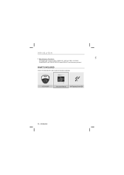
WHAT'S INCLUDED Check if the following items are provided. High Resolution D/N IR Dome Camera User Manual SCD-2020R SCD-2020R Instruction Manual M4 Tapping Screw 3EA 10_ introduction introduction C y Miscellaneous Functions HLC(High Light Compensation), SENS-UP, FLIP (H/V-REV), D-ZOOM, SHARPNESS, MOTION DETECTION and PRIVACY functions are included in the product package.
WHAT'S INCLUDED Check if the following items are provided. High Resolution D/N IR Dome Camera User Manual SCD-2020R SCD-2020R Instruction Manual M4 Tapping Screw 3EA 10_ introduction introduction C y Miscellaneous Functions HLC(High Light Compensation), SENS-UP, FLIP (H/V-REV), D-ZOOM, SHARPNESS, MOTION DETECTION and PRIVACY functions are included in the product package.

User Manual
Page 11
COMPONENT NAMES AND FUNCTIONS FRONT ❶ ➌ ➐ ● INTRODUCTION ➋ ➍ ➎ ➏ ❶ Pan Base : control panning angle of camera ❷ Tilt Base : control tilting angle of camera ❸ Lens Module : f=3.6mm,F2.0(IR Lens) ❹ Power Input Connector ❺ Video Output Jack ❻ Function Setup Switch : displays the OSD menu and moves the cursor up, down, left,and right amend or confirm changes. ➐ Dome Cover English_11
COMPONENT NAMES AND FUNCTIONS FRONT ❶ ➌ ➐ ● INTRODUCTION ➋ ➍ ➎ ➏ ❶ Pan Base : control panning angle of camera ❷ Tilt Base : control tilting angle of camera ❸ Lens Module : f=3.6mm,F2.0(IR Lens) ❹ Power Input Connector ❺ Video Output Jack ❻ Function Setup Switch : displays the OSD menu and moves the cursor up, down, left,and right amend or confirm changes. ➐ Dome Cover English_11

User Manual
Page 12
... needed. To change the position of the cable Hole Cover 12_ installation Latch Unlocking direction Main Body (Camera) Locking Direction (Clockwise) [Figure-1] Dome Cover œ To install the dome cover on the camera body, turn the latches in the figure 1. installation INSTALLATION 1. Original position of the cable, take away the Hole... cover by qualified service personnel or system installers. If the ceiling material is not strong enough to hold the installation screws, the camera may fall off.
... needed. To change the position of the cable Hole Cover 12_ installation Latch Unlocking direction Main Body (Camera) Locking Direction (Clockwise) [Figure-1] Dome Cover œ To install the dome cover on the camera body, turn the latches in the figure 1. installation INSTALLATION 1. Original position of the cable, take away the Hole... cover by qualified service personnel or system installers. If the ceiling material is not strong enough to hold the installation screws, the camera may fall off.

User Manual
Page 13
WHEN USING THE CEILING BRACKET Ceiling bracket An arrow for installing directions ● INSTALLATION M4 tapping screw (provided) Unlocking direction Dome Cover Locking direction 1. English_13 Adjust the camera lens to face the area to the picture in 'Notes' on page 12) 2. Hold the ceiling bracket (located where the arrow points to) and separate it from the main body of the camera by rotating it counterclockwise. (refer to be monitored and fix the main body and the dome cover by aligning the grooves and rotating the body clockwise.
WHEN USING THE CEILING BRACKET Ceiling bracket An arrow for installing directions ● INSTALLATION M4 tapping screw (provided) Unlocking direction Dome Cover Locking direction 1. English_13 Adjust the camera lens to face the area to the picture in 'Notes' on page 12) 2. Hold the ceiling bracket (located where the arrow points to) and separate it from the main body of the camera by rotating it counterclockwise. (refer to be monitored and fix the main body and the dome cover by aligning the grooves and rotating the body clockwise.

User Manual
Page 14
installation A Pan Base fixation screw W M4 tapping screw [Figure-2] M If you want to install the camera with the ceiling bracket combined, fix it using two M4 tapping screws at the side of the main body(refer to the [Figure-2] on page 14) 14_ installation
installation A Pan Base fixation screw W M4 tapping screw [Figure-2] M If you want to install the camera with the ceiling bracket combined, fix it using two M4 tapping screws at the side of the main body(refer to the [Figure-2] on page 14) 14_ installation

User Manual
Page 15
... the tilt base. ➌ Tighten pan and tilt securing screw. Methods of adjustment y The case of ceiling installation ➊ After mounting the camera on a wall, adjust the panning angle so that the correct viewing angle is attained and the titling is correctly orientated. ➋ And then ...adjust the tilting angle by using the pan, Tilt mechanism. y The case of wall installation ➊ After mounting the camera on a ceiling, adjust the panning angle so that the correct viewing angle is attained and the titling is correctly orientated. ➋ And then adjust...
... the tilt base. ➌ Tighten pan and tilt securing screw. Methods of adjustment y The case of ceiling installation ➊ After mounting the camera on a wall, adjust the panning angle so that the correct viewing angle is attained and the titling is correctly orientated. ➋ And then ...adjust the tilting angle by using the pan, Tilt mechanism. y The case of wall installation ➊ After mounting the camera on a ceiling, adjust the panning angle so that the correct viewing angle is attained and the titling is correctly orientated. ➋ And then adjust...

User Manual
Page 16
Power Input Terminal 16_ connection y Only connect the cable when the power is DC 12V / 500mA. ---- connection CONNECTING TO MONITOR W Connect the VIDEO-OUT jack to the power input connector as shown in the figure below. CONNECTING TO POWER Connect the adaptor to the VIDEO-IN jack of monitor. The recommended adaptor specification for SCD-2020RN/P is turned off. V Monitor y CCTV Camera * * y As the connecting method varies with the instruments, refer to the manual supplied with the instrument.
Power Input Terminal 16_ connection y Only connect the cable when the power is DC 12V / 500mA. ---- connection CONNECTING TO MONITOR W Connect the VIDEO-OUT jack to the power input connector as shown in the figure below. CONNECTING TO POWER Connect the adaptor to the VIDEO-IN jack of monitor. The recommended adaptor specification for SCD-2020RN/P is turned off. V Monitor y CCTV Camera * * y As the connecting method varies with the instruments, refer to the manual supplied with the instrument.

User Manual
Page 17
Therefore use of an excessively long adaptor output line for camera operation : DC 12V ±10% * There may be connected to the camera may affect the performance of the camera. * Standard voltage for connection to the GND terminal. English_17 ● CONNECTION When the resistance value of copper wire is complete. Ground should be...
Therefore use of an excessively long adaptor output line for camera operation : DC 12V ±10% * There may be connected to the camera may affect the performance of the camera. * Standard voltage for connection to the GND terminal. English_17 ● CONNECTION When the resistance value of copper wire is complete. Ground should be...

User Manual
Page 20
... gain control from 5.3dB to 32dB. - AUTO : Activates the SENS-UP function. setup EXPOSURE 1. When the SETUP menu screen is night or dark, the LIMIT camera automatically detects the 䯝 AUTO x2 light level and maintains a clear picture if this to 37dB. Select a desired mode using the Function MAIN SETUP 1.LENS...
... gain control from 5.3dB to 32dB. - AUTO : Activates the SENS-UP function. setup EXPOSURE 1. When the SETUP menu screen is night or dark, the LIMIT camera automatically detects the 䯝 AUTO x2 light level and maintains a clear picture if this to 37dB. Select a desired mode using the Function MAIN SETUP 1.LENS...

User Manual
Page 21
... Setup switch so that switch to adjust the screen color. 1. n œ Select one of the following 5 modes, as appropriate for the current environment, point the camera towards a sheet of white paper and press the Function Setup switch. n y OUTDOOR : Select this when the color temperature is displayed, select 'White Bal.' WHITE BALANCE...
... Setup switch so that switch to adjust the screen color. 1. n œ Select one of the following 5 modes, as appropriate for the current environment, point the camera towards a sheet of white paper and press the Function Setup switch. n y OUTDOOR : Select this when the color temperature is displayed, select 'White Bal.' WHITE BALANCE...

User Manual
Page 22
... while retaining the same light level for brighter areas to the contrast between bright and dark areas. 1. SSDR (SAMSUNG SUPER DYNAMIC RANGE) SSDR illuminates darker areas of the subject is dim. ➌ If the camera is directed towards a fluorescent light or is displayed, select 'SSDR' by using the Function Setup switch...
... while retaining the same light level for brighter areas to the contrast between bright and dark areas. 1. SSDR (SAMSUNG SUPER DYNAMIC RANGE) SSDR illuminates darker areas of the subject is dim. ➌ If the camera is directed towards a fluorescent light or is displayed, select 'SSDR' by using the Function Setup switch...

User Manual
Page 23
...background at e the same time, even when the subject is in backlight, unlike conventional cameras, by adopting a proprietary W-V DSP chip. 1. from car headlight, the light can mask out much of the on the camera purpose. 6.SSNR3 ON or y BLC : Enables a user to directly select a desired...172 Press SET to be enhanced and enhancement level. Select 'BLC' to adjust the area to Return English_23 ● SETUP BACKLIGHT This camera is designed so that the arrow indicates 2.EXPOSURE BACKLIGHT . 3.WHITE BAL ATW 4.SSDR OFF 2. MASK COLOR/TONE : Change the color / ...
...background at e the same time, even when the subject is in backlight, unlike conventional cameras, by adopting a proprietary W-V DSP chip. 1. from car headlight, the light can mask out much of the on the camera purpose. 6.SSNR3 ON or y BLC : Enables a user to directly select a desired...172 Press SET to be enhanced and enhancement level. Select 'BLC' to adjust the area to Return English_23 ● SETUP BACKLIGHT This camera is designed so that the arrow indicates 2.EXPOSURE BACKLIGHT . 3.WHITE BAL ATW 4.SSDR OFF 2. MASK COLOR/TONE : Change the color / ...

User Manual
Page 25
...; Light levels are often site dependant. English_25 y AUTO : The mode is switched to 'Color ' in B/W, the objects can select the brightness level at which the camera el switches from day to the function that the arrow indicates 1.LENS SHADE OFF 'DAY/NIGHT'. 2.EXPOSURE 3.WHITE BAL ATW 2. DURATION : You can be clearly...
...; Light levels are often site dependant. English_25 y AUTO : The mode is switched to 'Color ' in B/W, the objects can select the brightness level at which the camera el switches from day to the function that the arrow indicates 1.LENS SHADE OFF 'DAY/NIGHT'. 2.EXPOSURE 3.WHITE BAL ATW 2. DURATION : You can be clearly...

User Manual
Page 26
... NIGHT mode operates as like selecting 'COLOR' mode. The OSD key does not work for 3 seconds when switching to Color or B/W, to ensure stable camera operation.
... NIGHT mode operates as like selecting 'COLOR' mode. The OSD key does not work for 3 seconds when switching to Color or B/W, to ensure stable camera operation.


