
Service Manual
Page 33
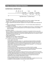
...,it will carry on , it will standby for a certain time and turns over the ice tray.At this time,the Ejection Standby time will be reset when it goes into F-Defrost during Ejection. -1st step : Ejection Temp Check Check whether the temp sensor is judged as the completion of ice making...
...,it will carry on , it will standby for a certain time and turns over the ice tray.At this time,the Ejection Standby time will be reset when it goes into F-Defrost during Ejection. -1st step : Ejection Temp Check Check whether the temp sensor is judged as the completion of ice making...
Service Manual
Page 37
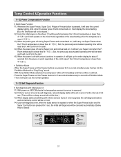
But, the previously accumulated operating time will be reset and it will count from the start . 1-4) When the power goes off during Super Freeze and comes back on hold. 1-4) Upon self-diagnosis error, when ... with at this time.) 1-3) When display LEDs are pressed for 5 s econds simultaneously, it only recognizes the self-diagnosis buttons and normal temp control will be reset and it will count from the power-on and off with initial power on 1-1) With power on, MICOM checks the temperature sensors for 5 seconds simultaneously...
But, the previously accumulated operating time will be reset and it will count from the start . 1-4) When the power goes off during Super Freeze and comes back on hold. 1-4) Upon self-diagnosis error, when ... with at this time.) 1-3) When display LEDs are pressed for 5 s econds simultaneously, it only recognizes the self-diagnosis buttons and normal temp control will be reset and it will count from the power-on and off with initial power on 1-1) With power on, MICOM checks the temperature sensors for 5 seconds simultaneously...
Service Manual
Page 46
OPERATION PRINCIPLES BY PARTS OF CIRCUIT 12-1) SOURCE POWER CIRCUIT 47 12-2) OSCILLATION CIRCUIT 47 12-3) RESET CIRCUIT 48 12-4) EEPROM DETECTION CIRCUIT 48 12-5) DOOR SWITCH DETECTON CIRCUIT 48 12-6) TEMP SENSING CIRCUIT 49 12-7) ICE MAKER OPERATION CIRCUIT 50 12-8) DISPLAY DRIVING CIRCUIT 51 12-9) LOAD DRIVING CIRCUIT 52 12-10) BUZZER CIRCUIT DIAGRAM 53 12-11) MODEL OPTION CIRCUIT 53 46 12.
OPERATION PRINCIPLES BY PARTS OF CIRCUIT 12-1) SOURCE POWER CIRCUIT 47 12-2) OSCILLATION CIRCUIT 47 12-3) RESET CIRCUIT 48 12-4) EEPROM DETECTION CIRCUIT 48 12-5) DOOR SWITCH DETECTON CIRCUIT 48 12-6) TEMP SENSING CIRCUIT 49 12-7) ICE MAKER OPERATION CIRCUIT 50 12-8) DISPLAY DRIVING CIRCUIT 51 12-9) LOAD DRIVING CIRCUIT 52 12-10) BUZZER CIRCUIT DIAGRAM 53 12-11) MODEL OPTION CIRCUIT 53 46 12.

Service Manual
Page 48
... voltage becomes "LOW" for several tens of ㎲ compared to 3.4~3.7V, the reset terminal voltage becomes "LOW". 12-4) EEPROM DETECTION CIRCUIT 1) A semiconductor memory EEPROM stores data remembering previous settings regardless of power-off,which are indispensable especially in ... voltage(DC 5V)at MICOM,and it maintains "HIGH"(Vcc Voltage)during normal operation. OPERATION PRINCIPLES BY PARTS OF CIRCUIT 12-3) RESET CIRCUIT Terminal Vcc Reset Power DC 5V DC 5V 1) RESET Circuit allows the whole program to go back to the initial setting by initializing parts such as the RAM in principle...
... voltage becomes "LOW" for several tens of ㎲ compared to 3.4~3.7V, the reset terminal voltage becomes "LOW". 12-4) EEPROM DETECTION CIRCUIT 1) A semiconductor memory EEPROM stores data remembering previous settings regardless of power-off,which are indispensable especially in ... voltage(DC 5V)at MICOM,and it maintains "HIGH"(Vcc Voltage)during normal operation. OPERATION PRINCIPLES BY PARTS OF CIRCUIT 12-3) RESET CIRCUIT Terminal Vcc Reset Power DC 5V DC 5V 1) RESET Circuit allows the whole program to go back to the initial setting by initializing parts such as the RAM in principle...
Service Manual
Page 75
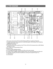
... sensor signals such as F/R Door S/W On/Off and sends them to the motor and detects the S/W on /off . 10. Circuit for the MICOM program control &Reset circuit initializing programs upon power on /off . 3. Buzzer Circuit 7. PCB DIAGRAM ⑧⑥ ⑨ ④ ⑫ ⑩ ① 1. EEPROM:It stores data. 4. AC is Relay...
... sensor signals such as F/R Door S/W On/Off and sends them to the motor and detects the S/W on /off . 10. Circuit for the MICOM program control &Reset circuit initializing programs upon power on /off . 3. Buzzer Circuit 7. PCB DIAGRAM ⑧⑥ ⑨ ④ ⑫ ⑩ ① 1. EEPROM:It stores data. 4. AC is Relay...
Service Manual
Page 77
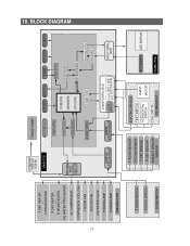
... DRIVING PART AC POWER INPUT POWER CORD AC100~240V MAIN PCB DRIVING PART CONTRIL CIRCUIT TRANSFORMER AC/DC POWER CIRCUIT OPTION CIRCUIT BUZZER CIRCUIT EEPROM RESET CIRCUIT OSCILLATOR CIRCUIT POWER CONTROL DRIVING PART CONTROL DOOR CONTROL AD CONVERT CONTROL TEST MODE CONTROL NORMAL MODE CONTROL STATUS CONTROL ICE MAKER CONTROL EEPROM...
... DRIVING PART AC POWER INPUT POWER CORD AC100~240V MAIN PCB DRIVING PART CONTRIL CIRCUIT TRANSFORMER AC/DC POWER CIRCUIT OPTION CIRCUIT BUZZER CIRCUIT EEPROM RESET CIRCUIT OSCILLATOR CIRCUIT POWER CONTROL DRIVING PART CONTROL DOOR CONTROL AD CONVERT CONTROL TEST MODE CONTROL NORMAL MODE CONTROL STATUS CONTROL ICE MAKER CONTROL EEPROM...


