

Service Manual
Page 1
Operating Instructions 4. Alignment and Adjustments 6. PCB Diagrams 9. MICROWAVE OVEN MW1150WA SERVICE Manual MICROWAVE OVEN CONTENTS 1. Schematic Diagrams SEA Specifications 3. Precaution 2. Disassembly and Reassembly 5. Trouble 7. Exploded Views and Parts List 8.
Operating Instructions 4. Alignment and Adjustments 6. PCB Diagrams 9. MICROWAVE OVEN MW1150WA SERVICE Manual MICROWAVE OVEN CONTENTS 1. Schematic Diagrams SEA Specifications 3. Precaution 2. Disassembly and Reassembly 5. Trouble 7. Exploded Views and Parts List 8.

Service Manual
Page 3
...switches, interlock monitor switch. 12. Examples: Lamp hole, ventilation slots. 9. To avoid any possible radiation hazard, replace parts in the drawings and parts lists of the B+ voltage interlocks. Never alter or add to remove or reinstall any semiconductor components or assemblies, drain .... Restore any of this manual. particularly children -- Make sure that there are replaced. Design Alteration Warning: Use exact replacement parts only, i.e., only those that all solid-state heat sinks are specified in accordance with the procedures described in this manual. Any...
...switches, interlock monitor switch. 12. Examples: Lamp hole, ventilation slots. 9. To avoid any possible radiation hazard, replace parts in the drawings and parts lists of the B+ voltage interlocks. Never alter or add to remove or reinstall any semiconductor components or assemblies, drain .... Restore any of this manual. particularly children -- Make sure that there are replaced. Design Alteration Warning: Use exact replacement parts only, i.e., only those that all solid-state heat sinks are specified in accordance with the procedures described in this manual. Any...

Service Manual
Page 4
... sure that the power is disconnected. 18. When connecting the oven to a 15A, make sure that circuit breaker can operate. 1-3 Special High Voltage Precautions 1. V. A replacement part that does not have the same ratings, especially for safety are critical for flame resistance and dielectric strength specifications. High Voltage Warning Do not attempt...
... sure that the power is disconnected. 18. When connecting the oven to a 15A, make sure that circuit breaker can operate. 1-3 Special High Voltage Precautions 1. V. A replacement part that does not have the same ratings, especially for safety are critical for flame resistance and dielectric strength specifications. High Voltage Warning Do not attempt...
Service Manual
Page 7
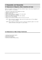
... replacing the magnetron, be sure to remount the magnetron gasket in the correct position and make sure that its antenna does not hit any adjacent parts, or it may be damaged. Disconnect all lead wires from the magnetron and lamp. 2. Remove the mounting bolts. 4. Reconnect the leads correctly and firmly. Remove...
... replacing the magnetron, be sure to remount the magnetron gasket in the correct position and make sure that its antenna does not hit any adjacent parts, or it may be damaged. Disconnect all lead wires from the magnetron and lamp. 2. Remove the mounting bolts. 4. Reconnect the leads correctly and firmly. Remove...
Service Manual
Page 9
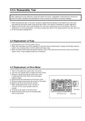
...If the door assembly is defective. 4-5 Replacement of Drive Motor 1. When the above three switches operate properly, check if any other part such as to the bottom line of the oven face plate by the operation of interlock monitor switch failure, replace the primary interlock... the drive motor and the coupler. 7. Screw the drive motor cover to the drive motor. 9. 4-3-4 Reassembly Test After replacement of the defective component parts of the door, reassemble it in the direction necessary for proper installation and adjustment so as the control circuit board, blower motor or high voltage...
...If the door assembly is defective. 4-5 Replacement of Drive Motor 1. When the above three switches operate properly, check if any other part such as to the bottom line of the oven face plate by the operation of interlock monitor switch failure, replace the primary interlock... the drive motor and the coupler. 7. Screw the drive motor cover to the drive motor. 9. 4-3-4 Reassembly Test After replacement of the defective component parts of the door, reassemble it in the direction necessary for proper installation and adjustment so as the control circuit board, blower motor or high voltage...

Service Manual
Page 12
... meter leads and read the resistance. Then follow the adjustment procedures below. Secondary Interlock Switch 3. An open capacitor will be sure to use the correct part number for play in the other direction. 5-6 Main Relay and Power Control Relay 1. 5-4 High Voltage Capacitor 1. Set the power level set at the highest resistance... smoothly after the start pad is pressed. 5-7 Adjustment of Secondary Switch, Door Sensing Switch and Monitor Switch Precaution For continued protection against radiation hazard, replace parts in the door by pulling the door assembly.
... meter leads and read the resistance. Then follow the adjustment procedures below. Secondary Interlock Switch 3. An open capacitor will be sure to use the correct part number for play in the other direction. 5-6 Main Relay and Power Control Relay 1. 5-4 High Voltage Capacitor 1. Set the power level set at the highest resistance... smoothly after the start pad is pressed. 5-7 Adjustment of Secondary Switch, Door Sensing Switch and Monitor Switch Precaution For continued protection against radiation hazard, replace parts in the door by pulling the door assembly.

Service Manual
Page 13
... 41seconds exactly. (3 seconds included as a holding time of Magnetron CAUTION MICROWAVE RADIATION PERSONNEL SHOULD NOT ALLOW EXPOSURE TO MICROWAVE RADIATION FROM MICROWAVE GENERATOR OR OTHER PARTS CONDUCTING MICROWAVE ENERGY. Normal temperature rise for this model is marginal. When heating is obtained by performing a water temperature rise test. Fill the one liter...
... 41seconds exactly. (3 seconds included as a holding time of Magnetron CAUTION MICROWAVE RADIATION PERSONNEL SHOULD NOT ALLOW EXPOSURE TO MICROWAVE RADIATION FROM MICROWAVE GENERATOR OR OTHER PARTS CONDUCTING MICROWAVE ENERGY. Normal temperature rise for this model is marginal. When heating is obtained by performing a water temperature rise test. Fill the one liter...

Service Manual
Page 14
... a corner of the door, keep the data. 2) If the radiation leakage is more than 4 mW/cm 2 after determining that all parts are in good condition, functioning properly and the identical parts are replaced as shown in this may cause damage to the probe. 4) Follow the recommendation of the manufacturer of the microwave...
... a corner of the door, keep the data. 2) If the radiation leakage is more than 4 mW/cm 2 after determining that all parts are in good condition, functioning properly and the identical parts are replaced as shown in this may cause damage to the probe. 4) Follow the recommendation of the manufacturer of the microwave...

Service Manual
Page 15
... diode and magnetron also. Key input is defective. Replace PCB main. BE CAREFUL OF THE HIGH VOLTAGE CIRCUIT. 3. DO NOT TOUCH ANY PART OF THE CIRCUIT OR THE CONTROL CIRCUIT BOARD, SINCE STATIC DISCHARGE MAY DAMAGE IT. Oven does not accept key input (Program) 1. Timer ... high voltage components H.V.Transformer H.V. 6. Replace PCB main. WHEN CHECKING THE CONTINUITY OF THE SWITCHES OR TRANSFORMER, DISCONNECT ONE LEAD WIRE FROM THESE PARTS AND THEN CHECK CONTINUITY WITHOUT THE POWER SOURCE ON. No display and no microwave oscillation. (No heat while oven lamp and fan motor turn on...
... diode and magnetron also. Key input is defective. Replace PCB main. BE CAREFUL OF THE HIGH VOLTAGE CIRCUIT. 3. DO NOT TOUCH ANY PART OF THE CIRCUIT OR THE CONTROL CIRCUIT BOARD, SINCE STATIC DISCHARGE MAY DAMAGE IT. Oven does not accept key input (Program) 1. Timer ... high voltage components H.V.Transformer H.V. 6. Replace PCB main. WHEN CHECKING THE CONTINUITY OF THE SWITCHES OR TRANSFORMER, DISCONNECT ONE LEAD WIRE FROM THESE PARTS AND THEN CHECK CONTINUITY WITHOUT THE POWER SOURCE ON. No display and no microwave oscillation. (No heat while oven lamp and fan motor turn on...

Service Manual
Page 16
... not start. 1. Tighten screws of magnetron Consult electrician. Oven stops operation during cooking 1. Open or loose wiring of the food with metallic trimming. Wrap thinner parts of Secondary interlock switch 2. Fan motor turns on 1. Replace PCB main. Shorted H.V.Diode Tighten screws of turntable motor. 2. Open or loose wiring of fan motor...
... not start. 1. Tighten screws of magnetron Consult electrician. Oven stops operation during cooking 1. Open or loose wiring of the food with metallic trimming. Wrap thinner parts of Secondary interlock switch 2. Fan motor turns on 1. Replace PCB main. Shorted H.V.Diode Tighten screws of turntable motor. 2. Open or loose wiring of fan motor...

Service Manual
Page 17
Exploded Views and Parts List 7-1 Exploded Views MD11 MD04 MD05 MD03 MD02 MD06 MD07 MD10 MM01 MM171 MM55 MM34 MM07 MM06 MM03 MD01 MM10 MM17 MC06 MC03 MC02 MC05 MC04 MM16 MM22 MM132 MM28 MC01 MM13 MB01 MB03 MB05 MM102 MM14 MB02 MM09 MB04 MB08 MM29 MM30 MC07 MC13 MM27 MM18 MM19 MM20 MM31 MM08 7.
Exploded Views and Parts List 7-1 Exploded Views MD11 MD04 MD05 MD03 MD02 MD06 MD07 MD10 MM01 MM171 MM55 MM34 MM07 MM06 MM03 MD01 MM10 MM17 MC06 MC03 MC02 MC05 MC04 MM16 MM22 MM132 MM28 MC01 MM13 MB01 MB03 MB05 MM102 MM14 MB02 MM09 MB04 MB08 MM29 MM30 MC07 MC13 MM27 MM18 MM19 MM20 MM31 MM08 7.

Service Manual
Page 18
...,6.35x31.3mm Q'ty Remark 1 1 MONITOR 1 SEC-S/W 1 1 1 DOOR-S/W 1 1 1 1 1 1 1 CV/AIR 1 1 1 1 1 1 CAVITY 1 1 1 1 2 1 1 1 1 1 1 Code No. MM13 DE66-90113A LEVER-DOOR PP(TB53-GH41),T2.5,-,-,12g,NTR,3RD-W,- 7-2 Main Parts List No. MM03 DE39-00278A WIRE HARNESS-A MW1255WA,-,120V60HZ,-,-,-,-,NC2000-1.2 2-TCO MM06 DE96-00100A ASSY-MOTOR FAN SMF-NC2UA1,120V60HZ,2800RPM,SJ0390,10MM MM07 DE39...
...,6.35x31.3mm Q'ty Remark 1 1 MONITOR 1 SEC-S/W 1 1 1 DOOR-S/W 1 1 1 1 1 1 1 CV/AIR 1 1 1 1 1 1 CAVITY 1 1 1 1 2 1 1 1 1 1 1 Code No. MM13 DE66-90113A LEVER-DOOR PP(TB53-GH41),T2.5,-,-,12g,NTR,3RD-W,- 7-2 Main Parts List No. MM03 DE39-00278A WIRE HARNESS-A MW1255WA,-,120V60HZ,-,-,-,-,NC2000-1.2 2-TCO MM06 DE96-00100A ASSY-MOTOR FAN SMF-NC2UA1,120V60HZ,2800RPM,SJ0390,10MM MM07 DE39...

Service Manual
Page 20
... Remark 4 MGT 4 TNS-HV 4 B-PLTE 2 BD-LAT 1 CN-BOX 1 CV/AIR 1 CVT-TCO 2 MO-FAN 1 P-C-EA 2 PN/OUT 1 S-M-EA 1 TCO 1 M/DRIV 2 O/PANEL 1 PCB 1 HVC 7-4 Standard Parts List Code No.
... Remark 4 MGT 4 TNS-HV 4 B-PLTE 2 BD-LAT 1 CN-BOX 1 CV/AIR 1 CVT-TCO 2 MO-FAN 1 P-C-EA 2 PN/OUT 1 S-M-EA 1 TCO 1 M/DRIV 2 O/PANEL 1 PCB 1 HVC 7-4 Standard Parts List Code No.


