User Manual (ENGLISH)
Page 36
...see an (error) message on the screen when the monitor is connected properly, check to see if the monitor status is on, reboot the computer to see the initial screen (the login screen), which can handle properly. If the power is set to analog. You can see this section ... remedy any problems yourself. If the display exceeds SXGA or 75 Symptom No images on the monitor. Check the power cord connection and supply. Check List Solutions Is the power cord connected properly? Can you see "Check Signal Cable" on the screen? (Connected using the D-sub cable) Check the signal cable...
...see an (error) message on the screen when the monitor is connected properly, check to see if the monitor status is on, reboot the computer to see the initial screen (the login screen), which can handle properly. If the power is set to analog. You can see this section ... remedy any problems yourself. If the display exceeds SXGA or 75 Symptom No images on the monitor. Check the power cord connection and supply. Check List Solutions Is the power cord connected properly? Can you see "Check Signal Cable" on the screen? (Connected using the D-sub cable) Check the signal cable...
User Manual (ENGLISH)
Page 41
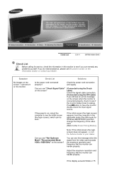
General General Model Name SyncMaster 2220WM LCD Panel Size 22 " Wide Diagonal (55.9 cm) Display area 473.76 mm(H) x 296.1 mm(V) Pixel Pitch 0.282 mm (H) x 0.282 mm (V) Synchronization Horizontal 30 ~ 81 kHz Vertical 56...(Digital Visual Interface) Compliant Digital RGB 0.7 Vp-p ± 5 % separate H/V sync, Composite, SOG TTL level (V high ≥ 2.0 V, V low ≤ 0.8 V) Maximum Pixel Clock 150 MHz Power Supply AC 100 - 240 V~ (+/- 10 %), 50/60 Hz Signal Cable 15pin-to-15pin D-sub cable, Detachable DVI-D to DVI-D connector, Detachable (option) Dimensions (WxHxD) / Weigh
General General Model Name SyncMaster 2220WM LCD Panel Size 22 " Wide Diagonal (55.9 cm) Display area 473.76 mm(H) x 296.1 mm(V) Pixel Pitch 0.282 mm (H) x 0.282 mm (V) Synchronization Horizontal 30 ~ 81 kHz Vertical 56...(Digital Visual Interface) Compliant Digital RGB 0.7 Vp-p ± 5 % separate H/V sync, Composite, SOG TTL level (V high ≥ 2.0 V, V low ≤ 0.8 V) Maximum Pixel Clock 150 MHz Power Supply AC 100 - 240 V~ (+/- 10 %), 50/60 Hz Signal Cable 15pin-to-15pin D-sub cable, Detachable DVI-D to DVI-D connector, Detachable (option) Dimensions (WxHxD) / Weigh
Service Manual
Page 42
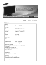
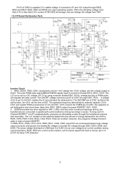
... R,G,B signals and convert them to which is a two-way serial bus of the MCU and then con- The digital value (data) is supplied to the panel in normal conditions. Inverter: A conversion device that is a clue to proper reso- or downscaling that supports communications across the integrated... Key 3.3V Regulator 1.8V Regulator 14.318MH z 1MB Flash 24C04 EEPROM IP Board 5V Regulator 1. Power MosFET: The IP board receives 5V and outputs a lower voltage in DPMS mode and supplies the whole 5V for mutual communications, which key is controlled by the A/D converter of the chip....
... R,G,B signals and convert them to which is a two-way serial bus of the MCU and then con- The digital value (data) is supplied to the panel in normal conditions. Inverter: A conversion device that is a clue to proper reso- or downscaling that supports communications across the integrated... Key 3.3V Regulator 1.8V Regulator 14.318MH z 1MB Flash 24C04 EEPROM IP Board 5V Regulator 1. Power MosFET: The IP board receives 5V and outputs a lower voltage in DPMS mode and supplies the whole 5V for mutual communications, which key is controlled by the A/D converter of the chip....
Service Manual
Page 43
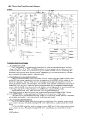
...and the Vcc pin capacitor is used to smooth the wave from zero to the maximum value over approximately 4ms. If no external feedback/supply current is fed into the FB pin by C801 and C802. The soft-start , the current Setpoint will prevent MOSFET Q804 from shock...cycle control. 1.3 DC_5V and DC_14V Output Circuit For DC 5V, D805 is a highly integrated PWM controller. 12-2 IP Board Part(Power) Schematic Diagrams Power Switching Mode Power Supply 1.1 AC Current Input Circuit P801 is used to rectify the inducted current. R801 and R802 joined between two inputting main circuit to prevent...
...and the Vcc pin capacitor is used to smooth the wave from zero to the maximum value over approximately 4ms. If no external feedback/supply current is fed into the FB pin by C801 and C802. The soft-start , the current Setpoint will prevent MOSFET Q804 from shock...cycle control. 1.3 DC_5V and DC_14V Output Circuit For DC 5V, D805 is a highly integrated PWM controller. 12-2 IP Board Part(Power) Schematic Diagrams Power Switching Mode Power Supply 1.1 AC Current Input Circuit P801 is used to rectify the inducted current. R801 and R802 joined between two inputting main circuit to prevent...
Service Manual
Page 44
... TIMER pin of IC501, the capacitor to 5V and 14V output through R822, R823 and R824. Turning each transformer driving two lamps in drain of power MOSFET. 3. R506, R510, C509, C513, C514, R525, R531, C528, C525, and C527 are connected in push pull topology driving, two... transformers are connected between high voltage output connector and ground, the divided AC voltage is supplied 2.5-v stable voltage. DRV!, DRV2 output for U501, U502, and they suppress Voltage transient spike in series. When the sampling voltage more than...
... TIMER pin of IC501, the capacitor to 5V and 14V output through R822, R823 and R824. Turning each transformer driving two lamps in drain of power MOSFET. 3. R506, R510, C509, C513, C514, R525, R531, C528, C525, and C527 are connected in push pull topology driving, two... transformers are connected between high voltage output connector and ground, the divided AC voltage is supplied 2.5-v stable voltage. DRV!, DRV2 output for U501, U502, and they suppress Voltage transient spike in series. When the sampling voltage more than...
Service Manual
Page 45
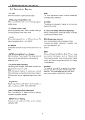
...Auto Configuration(Auto adjustment) This is composed of the same color is called the 'Dot Pitch'. 13 Reference Information 13-1 Technical Terms -TFT-LCD Thin film Transistor Liquid Crystal Display -ADC(Analog to Digital Converter) This is a communication method between a Host Computer and related equipment. AC... with Video clock -Inverter Device that changes the number of transmission method for Digital. The distance between PC and Monitor. -EDID Extended Display Identification Data PC can be used to DC(+12V or 14V) -SMPS(Switching Mode Power Supply) Switching Mode Power supply.
...Auto Configuration(Auto adjustment) This is composed of the same color is called the 'Dot Pitch'. 13 Reference Information 13-1 Technical Terms -TFT-LCD Thin film Transistor Liquid Crystal Display -ADC(Analog to Digital Converter) This is a communication method between a Host Computer and related equipment. AC... with Video clock -Inverter Device that changes the number of transmission method for Digital. The distance between PC and Monitor. -EDID Extended Display Identification Data PC can be used to DC(+12V or 14V) -SMPS(Switching Mode Power Supply) Switching Mode Power supply.


