Operation Manual
Page 2
...61550; Warranty...2 General Safety Rules...3 - 4 Specific Safety Rules...4 Symbols...5 Electrical...6 - 7 Features...7 Assembly...8 - 9 Operation...9 - 11 Maintenance...12 Figure numbers (illustrations)...13 - 17 Parts Ordering / Service...Back page INTRODUCTION This... This warranty gives you specific legal rights, and you may also have been given top priority in this warranty. warranty RYOBI® POWER TOOL - Batteries are warranted for a period of two years from the date of purchase, you by...
...61550; Warranty...2 General Safety Rules...3 - 4 Specific Safety Rules...4 Symbols...5 Electrical...6 - 7 Features...7 Assembly...8 - 9 Operation...9 - 11 Maintenance...12 Figure numbers (illustrations)...13 - 17 Parts Ordering / Service...Back page INTRODUCTION This... This warranty gives you specific legal rights, and you may also have been given top priority in this warranty. warranty RYOBI® POWER TOOL - Batteries are warranted for a period of two years from the date of purchase, you by...
Operation Manual
Page 8
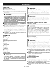
.... Remove arbor nut, outer wheel washer, and cutting- ing. English warning: Do not attempt to modify this list are already assembled to power supply until the parts are damaged or missing, please call 1-800-525-2579 for accurate cutting. WARNING: Do not connect to ...: Remove bevel table. Slide the hex wrench over the wheel arbor nut. WARNING: Do not use wheels that have been improperly assembled could result in contact with the flats on a level work surface. WARNING: A 7 in a hazardous condition leading to specific procedures explained in this manual...
.... Remove arbor nut, outer wheel washer, and cutting- ing. English warning: Do not attempt to modify this list are already assembled to power supply until the parts are damaged or missing, please call 1-800-525-2579 for accurate cutting. WARNING: Do not connect to ...: Remove bevel table. Slide the hex wrench over the wheel arbor nut. WARNING: Do not use wheels that have been improperly assembled could result in contact with the flats on a level work surface. WARNING: A 7 in a hazardous condition leading to specific procedures explained in this manual...
Operation Manual
Page 9
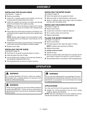
... using angle scale and tighten securely with local regulations. English Thread splash hood knob onto bolt and tighten to table and slightly above tile thickness. ASSEMBLY Installing the splash hood See Figure 6 - 7, page 14. Remove bevel table. Install the L-shaped splash hood bracket into the lip located under the...
... using angle scale and tighten securely with local regulations. English Thread splash hood knob onto bolt and tighten to table and slightly above tile thickness. ASSEMBLY Installing the splash hood See Figure 6 - 7, page 14. Remove bevel table. Install the L-shaped splash hood bracket into the lip located under the...


