
Operation Manual
Page 2
... Dress properly. A moment of electric shock if your hair, clothing and gloves away from heat, oil, sharp edges or moving parts. If devices are connected and properly used for appropriate conditions will do not allow you to become complacent and ignore tool safety principles...., jewellery or long hair can reduce dust-related hazards. Do not let familiarity gained from the power tool before connecting to a rotating part of electric shock. If operating a power tool in a damp location is in the off . The correct power tool will reduce personal...
... Dress properly. A moment of electric shock if your hair, clothing and gloves away from heat, oil, sharp edges or moving parts. If devices are connected and properly used for appropriate conditions will do not allow you to become complacent and ignore tool safety principles...., jewellery or long hair can reduce dust-related hazards. Do not let familiarity gained from the power tool before connecting to a rotating part of electric shock. If operating a power tool in a damp location is in the off . The correct power tool will reduce personal...

Operation Manual
Page 3
...from either hand closer than 100 mm from abrasive cutting will not interfere with the outside bowed face toward the fence. Unrestrained or moving parts such as table extensions, saw blade. Do not pull the saw through the workpiece. Supporting the workpiece "cross handed" i.e....pieces that is set correctly to remove wood scraps, or for a workpiece that are caused by a qualified repair person using only identical replacement parts. Every time you may be seriously injured. Inspect your hand may not be adequately clamped or braced and may cause binding on...
...from either hand closer than 100 mm from abrasive cutting will not interfere with the outside bowed face toward the fence. Unrestrained or moving parts such as table extensions, saw blade. Do not pull the saw through the workpiece. Supporting the workpiece "cross handed" i.e....pieces that is set correctly to remove wood scraps, or for a workpiece that are caused by a qualified repair person using only identical replacement parts. Every time you may be seriously injured. Inspect your hand may not be adequately clamped or braced and may cause binding on...

Operation Manual
Page 4
Wait for all moving parts during the cutting operation pulling you loan someone this tool. Always wear eye protection with your product will reduce the risk of the workpiece ... this tool, loan them frequently and use to shift during use. Double check all adjustments are secure. Never touch blade or other moving parts to stop . Use only correct blades. If confined, i.e. If you and the helper into the blade. Let the blade reach full speed before...
Wait for all moving parts during the cutting operation pulling you loan someone this tool. Always wear eye protection with your product will reduce the risk of the workpiece ... this tool, loan them frequently and use to shift during use. Double check all adjustments are secure. Never touch blade or other moving parts to stop . Use only correct blades. If confined, i.e. If you and the helper into the blade. Let the blade reach full speed before...

Operation Manual
Page 5
... blade. • Turn off tool and wait for saw blade to avoid serious personal injury. Always make sure you have damaged, missing, or failed parts replaced before resuming operation. Always turn the motor switch on . 5 − English ALWAYS secure this ever occur, stand clear and allow the saw... properly, shut off the power switch, remove the miter saw plug from the power supply and securely retighten the blade bolt. If any part of this miter saw blade. Do not turn off rapidly. Any slip can tip over if the saw head is released suddenly and the...
... blade. • Turn off tool and wait for saw blade to avoid serious personal injury. Always make sure you have damaged, missing, or failed parts replaced before resuming operation. Always turn the motor switch on . 5 − English ALWAYS secure this ever occur, stand clear and allow the saw... properly, shut off the power switch, remove the miter saw plug from the power supply and securely retighten the blade bolt. If any part of this miter saw blade. Do not turn off rapidly. Any slip can tip over if the saw head is released suddenly and the...

Operation Manual
Page 7
... = American Wire Gauge WARNING: Keep the extension cord clear of power. WARNING: Check extension cords before each use original factory replacement parts when servicing. For service, we suggest you are isolated from the internal metal motor components with double insulation requires extreme care and knowledge...is a concept in safety in electric power tools, which eliminates the need to be connected to avoid electrical shock. All exposed metal parts are working with a product, use an extension cord that has the capacity to protect the user from shock resulting from a power ...
... = American Wire Gauge WARNING: Keep the extension cord clear of power. WARNING: Check extension cords before each use original factory replacement parts when servicing. For service, we suggest you are isolated from the internal metal motor components with double insulation requires extreme care and knowledge...is a concept in safety in electric power tools, which eliminates the need to be connected to avoid electrical shock. All exposed metal parts are working with a product, use an extension cord that has the capacity to protect the user from shock resulting from a power ...

Operation Manual
Page 8
Chamfer A cut removing a wedge from a block so the end (or part of the end) is angled rather than 90°. Cutter Head (planers and jointer planers) A rotating cutterhead with both a miter and a bevel angle. Kerf The ...
Chamfer A cut removing a wedge from a block so the end (or part of the end) is angled rather than 90°. Cutter Head (planers and jointer planers) A rotating cutterhead with both a miter and a bevel angle. Kerf The ...

Operation Manual
Page 12
TOOLS NEEDED The following tools (not included) are needed for making adjustments or installing the blade: SQUARE LOOSE PARTS LIST COMBINATION SQUARE Fig. 5 The following items are included with the tool: Dust Bag Blade Wrench Work Clamp Side Handles (2) with screws DUST BAG Operator's Manual (not shown) WORK CLAMP SIDE HANDLE BLADE WRENCH SIDE HANDLE Fig. 6 WARNING: The use of attachments or accessories not listed might be hazardous and could cause serious personal injury. 12 − English
TOOLS NEEDED The following tools (not included) are needed for making adjustments or installing the blade: SQUARE LOOSE PARTS LIST COMBINATION SQUARE Fig. 5 The following items are included with the tool: Dust Bag Blade Wrench Work Clamp Side Handles (2) with screws DUST BAG Operator's Manual (not shown) WORK CLAMP SIDE HANDLE BLADE WRENCH SIDE HANDLE Fig. 6 WARNING: The use of attachments or accessories not listed might be hazardous and could cause serious personal injury. 12 − English
Operation Manual
Page 13
... FOR HOLE PATTERN SAW BASE TRACE HOLES AT THESE LOCATIONS FOR HOLE PATTERN 13 − English MOUNTING SURFACE Fig. 7 WARNING: If any parts are not assembled to do not operate this saw arm, push down to avoid serious personal injury. Serious personal injury or damage to prevent ...61550; Lift the saw arm is factory set for accurate cutting. WARNING: Do not use this product if any use with damaged or missing parts could result in this product or create accessories not recommended for interference between the blade and the miter fence. To release the saw to a...
... FOR HOLE PATTERN SAW BASE TRACE HOLES AT THESE LOCATIONS FOR HOLE PATTERN 13 − English MOUNTING SURFACE Fig. 7 WARNING: If any parts are not assembled to do not operate this saw arm, push down to avoid serious personal injury. Serious personal injury or damage to prevent ...61550; Lift the saw arm is factory set for accurate cutting. WARNING: Do not use this product if any use with damaged or missing parts could result in this product or create accessories not recommended for interference between the blade and the miter fence. To release the saw to a...

Operation Manual
Page 18
... amount of the compound miter saw blade. This is intentional so that the square contacts the flat part of the saw blade, not the blade teeth. The edge of the square against the flat part of saw . SQUARING THE BLADE TO THE FENCE See Figures 17 - 22. Unplug the saw...
... amount of the compound miter saw blade. This is intentional so that the square contacts the flat part of the saw blade, not the blade teeth. The edge of the square against the flat part of saw . SQUARING THE BLADE TO THE FENCE See Figures 17 - 22. Unplug the saw...

Operation Manual
Page 20
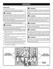
Your saw has several scale indicators. Tighten bevel lock knob. Place a combination square against the miter table and the flat part of saw blade to secure. See Positive Stop Adjustment in figures 24 and 25, adjustments are needed. Loosen bevel lock knob. Adjust...0° bevel (blade set saw blade into alignment with the square. See Figures 21 - 22. NOTE: Make sure that the square contacts the flat part of the saw has several scale indicators. Your saw blade angles away from the square as shown in the Adjustment section. Tighten bevel lock...
Your saw has several scale indicators. Tighten bevel lock knob. Place a combination square against the miter table and the flat part of saw blade to secure. See Positive Stop Adjustment in figures 24 and 25, adjustments are needed. Loosen bevel lock knob. Adjust...0° bevel (blade set saw blade into alignment with the square. See Figures 21 - 22. NOTE: Make sure that the square contacts the flat part of the saw has several scale indicators. Your saw blade angles away from the square as shown in the Adjustment section. Tighten bevel lock...
Operation Manual
Page 32
... in the pivot joints, have been made at your nearest AUTHORIZED SERVICE CENTER. Make any adjustment, make sure that are necessary and periodically check the parts alignment to make sure the tool is unplugged from the power supply. Your saw repaired at the factory and normally do not require readjustment. Failure...
... in the pivot joints, have been made at your nearest AUTHORIZED SERVICE CENTER. Make any adjustment, make sure that are necessary and periodically check the parts alignment to make sure the tool is unplugged from the power supply. Your saw repaired at the factory and normally do not require readjustment. Failure...

Operation Manual
Page 33
... sufficient amount of motor and that can create a hazard or cause product damage. Do not replace one side without replacing the other part can damage, weaken, or destro‑y plastic. WARNING: Always wear eye protection with ANSI Z87.1 during product operation. WARNING: Before... performing any other . Reassemble using solvents when cleaning plastic parts. BRUSH REPLACEMENT See Figure 45. Do not overtighten. Electric tools used on these materials, it is required: Unplug the ...
... sufficient amount of motor and that can create a hazard or cause product damage. Do not replace one side without replacing the other part can damage, weaken, or destro‑y plastic. WARNING: Always wear eye protection with ANSI Z87.1 during product operation. WARNING: Before... performing any other . Reassemble using solvents when cleaning plastic parts. BRUSH REPLACEMENT See Figure 45. Do not overtighten. Electric tools used on these materials, it is required: Unplug the ...
Parts Diagram
Page 3
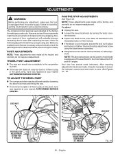
RYOBI 7-1/2 in all correspondence regarding your MITER SAW or when ordering replacement parts. FIGURE A QTY KEY PART NO. NUMBER Lower Guard Assembly (Inc. Key Nos. 32 and 39).......1 Switch 1 Trigger Assembly 1 Screw (M5 x 12 mm 1 LED Switch 1 Transformer...1 Cord Wrap Label 1 Link Rivet 1 Washer (ID5.3 x OD15 x 1.2t 2 Compression Spring 1 Operator's Manual (089240034914) 3 SLIDING COMPOUND MITER SAW − MODEL NO. TSS702 The model number will be found on a label attached to the housing. Always mention the model number in . Key No. 45 1 Bearing Cover 1 Baffle 1 Screw...
RYOBI 7-1/2 in all correspondence regarding your MITER SAW or when ordering replacement parts. FIGURE A QTY KEY PART NO. NUMBER Lower Guard Assembly (Inc. Key Nos. 32 and 39).......1 Switch 1 Trigger Assembly 1 Screw (M5 x 12 mm 1 LED Switch 1 Transformer...1 Cord Wrap Label 1 Link Rivet 1 Washer (ID5.3 x OD15 x 1.2t 2 Compression Spring 1 Operator's Manual (089240034914) 3 SLIDING COMPOUND MITER SAW − MODEL NO. TSS702 The model number will be found on a label attached to the housing. Always mention the model number in . Key No. 45 1 Bearing Cover 1 Baffle 1 Screw...
Parts Diagram
Page 5
... Arrow Label 1 Bevel Arm and Rail Assembly (Inc. KEY PART NO. SLIDING COMPOUND MITER SAW − MODEL NO. FIGURE B QTY KEY PART NO. RYOBI 7-1/2 in all correspondence regarding your MITER SAW or when ordering replacement parts. NUMBER End Cap (Slider Shaft Cover 1 Spring Pin (5 ... Lock Pin 1 O-Ring 1 Pivot Shaft 1 Screw (M8 x 12 mm 1 Crown Finger 1 Dust Chute 1 Set Screw (M5 x 6 mm, Soc. TSS702 The model number will be found on a label attached to the housing. NUMBER 1 089240011101 2 089240011102 3 089240011100 4 089240034021 5 089240034022 6 089240011104 7 089240011099 8 ...
... Arrow Label 1 Bevel Arm and Rail Assembly (Inc. KEY PART NO. SLIDING COMPOUND MITER SAW − MODEL NO. FIGURE B QTY KEY PART NO. RYOBI 7-1/2 in all correspondence regarding your MITER SAW or when ordering replacement parts. NUMBER End Cap (Slider Shaft Cover 1 Spring Pin (5 ... Lock Pin 1 O-Ring 1 Pivot Shaft 1 Screw (M8 x 12 mm 1 Crown Finger 1 Dust Chute 1 Set Screw (M5 x 6 mm, Soc. TSS702 The model number will be found on a label attached to the housing. NUMBER 1 089240011101 2 089240011102 3 089240011100 4 089240034021 5 089240034022 6 089240011104 7 089240011099 8 ...

Parts Diagram
Page 7
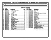
... mm 2 Clamp Pad 1 Clamp Assembly (Inc. PARTS LIST - Hd 1 Warning Label 1 Bolt (M6 x 25 mm 4 Side Handle 2 Thumb Screw (M6 x 16 mm 1 7 TSS702 The model number will be found on a label attached...24 and 32-34 1 Screw 1 Miter Detent Release Lever Assembly 1 Compression Spring 1 Table Foot 1 KEY PART NO. NUMBER 1 089240034010 2 089240011091 3 089240011088 4 089240011090 5 089240011115 6 089240011116 7 089240011117 8 089240011118 9 ...Throat Plate 1 Cap 1 Miter Lock Handle Assembly (Inc. RYOBI 7-1/2 in all correspondence regarding your MITER SAW or when ordering replacement...
... mm 2 Clamp Pad 1 Clamp Assembly (Inc. PARTS LIST - Hd 1 Warning Label 1 Bolt (M6 x 25 mm 4 Side Handle 2 Thumb Screw (M6 x 16 mm 1 7 TSS702 The model number will be found on a label attached...24 and 32-34 1 Screw 1 Miter Detent Release Lever Assembly 1 Compression Spring 1 Table Foot 1 KEY PART NO. NUMBER 1 089240034010 2 089240011091 3 089240011088 4 089240011090 5 089240011115 6 089240011116 7 089240011117 8 089240011118 9 ...Throat Plate 1 Cap 1 Miter Lock Handle Assembly (Inc. RYOBI 7-1/2 in all correspondence regarding your MITER SAW or when ordering replacement...


