User Manual
Page 4
...battery packs, see tool/appliance/ battery pack/charger correlation supplement 987000-432. When battery pack is not in use, keep it firmly against the fence as a backstop. Never start the saw table at a time. NEVER perform any operation freehand. Do not cut . MAKE SURE ...more than one terminal to power supply. EnsuRE the switch is tight and not making any medication. When servicing use the fence. 4 SPECIFIC SAFETY RULES FIRMLY CLAMP OR BOLT the tool to cut on the miter table and position it away from other metal objects...
...battery packs, see tool/appliance/ battery pack/charger correlation supplement 987000-432. When battery pack is not in use, keep it firmly against the fence as a backstop. Never start the saw table at a time. NEVER perform any operation freehand. Do not cut . MAKE SURE ...more than one terminal to power supply. EnsuRE the switch is tight and not making any medication. When servicing use the fence. 4 SPECIFIC SAFETY RULES FIRMLY CLAMP OR BOLT the tool to cut on the miter table and position it away from other metal objects...
User Manual
Page 7
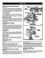
... 90° to hold the workpiece during cutting operations. Saw Blade Path The area over the jointer planer cutterhead during any angle to the fence. Cross Cut A cutting or shaping operation made with both a miter and a bevel angle. The blades or knives remove material from wood ... operation along the length of the blade. Through Sawing Any cutting operation where the blade extends completely through the thickness of a workpiece by a fence, miter gauge, or other than the blade, which the operation is mounted. Bevel Cut A cutting operation made at any operation. FPM or ...
... 90° to hold the workpiece during cutting operations. Saw Blade Path The area over the jointer planer cutterhead during any angle to the fence. Cross Cut A cutting or shaping operation made with both a miter and a bevel angle. The blades or knives remove material from wood ... operation along the length of the blade. Through Sawing Any cutting operation where the blade extends completely through the thickness of a workpiece by a fence, miter gauge, or other than the blade, which the operation is mounted. Bevel Cut A cutting operation made at any operation. FPM or ...
User Manual
Page 8
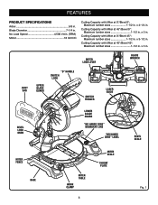
... Trigger laser guide Bevel Lock Knob Lower blade guard "NO HANDS ZONE" BOUNDARY LINE 45 30 33.9 15 0 1 2 3 4 5 "NO HANDS ZONE" LABEL bevel scale miter fence base 45 MITER TABLE WORK CLAMP 8 Miter Scale throat plate Fig. 1 FEATURES PRODUCT SPECIFICATIONS Arbor 5/8 in . x 4-1/4 in . Cutting Capacity with Miter at 45°/Bevel...
... Trigger laser guide Bevel Lock Knob Lower blade guard "NO HANDS ZONE" BOUNDARY LINE 45 30 33.9 15 0 1 2 3 4 5 "NO HANDS ZONE" LABEL bevel scale miter fence base 45 MITER TABLE WORK CLAMP 8 Miter Scale throat plate Fig. 1 FEATURES PRODUCT SPECIFICATIONS Arbor 5/8 in . x 4-1/4 in . Cutting Capacity with Miter at 45°/Bevel...
User Manual
Page 9
... are attempting. One end of the wrench is a phillips screwdriver and the other end is lowered into the workpiece. LASER GUIDE See Figure 2. MITER FENCE The miter fence on the compound miter saw 's base. The 15°, 22-1/2°, 31.62°, and 45° positive stops have been provided on . To...
... are attempting. One end of the wrench is a phillips screwdriver and the other end is lowered into the workpiece. LASER GUIDE See Figure 2. MITER FENCE The miter fence on the compound miter saw 's base. The 15°, 22-1/2°, 31.62°, and 45° positive stops have been provided on . To...
User Manual
Page 12
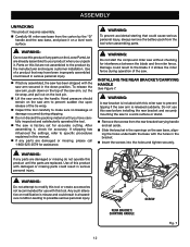
...Parts List are already assembled to your product when you have been improperly assembled could result to the blade if it strikes the miter fence during shipping. Do not discard the packing material until the parts are damaged or missing, please call 1-800-525-2579 ... factory set aside. Slide the bracket in serious personal injury. After assembling it, check for interference between the blade and the miter fence. Warning: If any parts are replaced. ASSEMBLY UNPACKING This product requires assembly. Carefully lift miter saw base from the carton by the...
...Parts List are already assembled to your product when you have been improperly assembled could result to the blade if it strikes the miter fence during shipping. Do not discard the packing material until the parts are damaged or missing, please call 1-800-525-2579 ... factory set aside. Slide the bracket in serious personal injury. After assembling it, check for interference between the blade and the miter fence. Warning: If any parts are replaced. ASSEMBLY UNPACKING This product requires assembly. Carefully lift miter saw base from the carton by the...
User Manual
Page 14
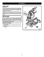
... out as needed. Always make sure there is very helpful when cutting compound miters. ASSEMBLY WORK CLAMP See Figure 10. The work clamp to the fence.
... out as needed. Always make sure there is very helpful when cutting compound miters. ASSEMBLY WORK CLAMP See Figure 10. The work clamp to the fence.
User Manual
Page 16
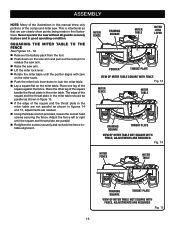
...; Rotate the miter table until the square and throat plate are needed. Using the blade wrench provided, loosen the socket head screws securing the fence. Place one leg of the square beside the throat plate in the miter table. The edge of the square and the throat plate in the... in the miter table are not parallel as shown in figures 14 and 15, adjustments are parallel. Retighten the screws securely and recheck the fence-totable alignment. ASSEMBLY Note: Many of the illustrations in this manual show points being made in good operating condition. MITER...
...; Rotate the miter table until the square and throat plate are needed. Using the blade wrench provided, loosen the socket head screws securing the fence. Place one leg of the square beside the throat plate in the miter table. The edge of the square and the throat plate in the... in the miter table are not parallel as shown in figures 14 and 15, adjustments are parallel. Retighten the screws securely and recheck the fence-totable alignment. ASSEMBLY Note: Many of the illustrations in this manual show points being made in good operating condition. MITER...
User Manual
Page 17
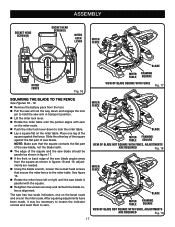
...61550; Using the blade wrench, loosen the socket head screws that secure the miter fence to zero. Slide the other leg of the square against the fence. See figure 16. Rotate the miter fence left or right until the pointer aligns with the square. Retighten the ...screws securely and recheck the blade-tofence alignment. MITER FENCE Blade MITER framing TABLE square VIEW OF Blade NOT SQUARE WITh FENCE, ADJUSTMENTS ARE REQUIRED Fig. 18 MITER FENCE Blade MITER framing TABLE square VIEW OF Blade NOT SQUARE WITH FENCE, ADJUSTMENTS ARE REQUIRED Fig. 19 17 Note: Make...
...61550; Using the blade wrench, loosen the socket head screws that secure the miter fence to zero. Slide the other leg of the square against the fence. See figure 16. Rotate the miter fence left or right until the pointer aligns with the square. Retighten the ...screws securely and recheck the blade-tofence alignment. MITER FENCE Blade MITER framing TABLE square VIEW OF Blade NOT SQUARE WITh FENCE, ADJUSTMENTS ARE REQUIRED Fig. 18 MITER FENCE Blade MITER framing TABLE square VIEW OF Blade NOT SQUARE WITH FENCE, ADJUSTMENTS ARE REQUIRED Fig. 19 17 Note: Make...
User Manual
Page 18
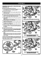
... all the way down to lock the miter table. Loosen bevel lock knob and set 90° to miter table). BEVEL LOCK KNOB MITER FENCE blade combination square MITER TABLE CORRECT VIEW OF Blade SQUARE WITH Miter Table Fig. 21 BEVEL LOCK KNOB MITER... NOT SQUARe WITH Miter Table, ADJUSTMENTS ARE REQUIRED Fig. 22 BEVEL LOCK KNOB 45 30 33.9 15 0 1 2 3 4 5 BEVEL SCALE 45 Miter SCALE INDICATOR SCREW MITER FENCE scale indicator combination square blade MITER TABLE Fig. 20 18 VIEW OF Blade NOT SQUARE WITH Miter Table, ADJUSTMENTS ARE REQUIRED Fig. 23 ASSEMBLY SQUARING...
... all the way down to lock the miter table. Loosen bevel lock knob and set 90° to miter table). BEVEL LOCK KNOB MITER FENCE blade combination square MITER TABLE CORRECT VIEW OF Blade SQUARE WITH Miter Table Fig. 21 BEVEL LOCK KNOB MITER... NOT SQUARe WITH Miter Table, ADJUSTMENTS ARE REQUIRED Fig. 22 BEVEL LOCK KNOB 45 30 33.9 15 0 1 2 3 4 5 BEVEL SCALE 45 Miter SCALE INDICATOR SCREW MITER FENCE scale indicator combination square blade MITER TABLE Fig. 20 18 VIEW OF Blade NOT SQUARE WITH Miter Table, ADJUSTMENTS ARE REQUIRED Fig. 23 ASSEMBLY SQUARING...
User Manual
Page 20
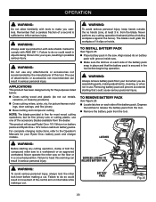
...miters, joints, etc. from the blade. for fine joinery cuts or cutting plastic, use of the accessory blades available from your Ryobi One+ battery pack and charger models. The blade could cause serious personal injury. Failure to a workbench or an approved workstand....Before starting that a careless fraction of this warning can result in use any cutting operation freehand (without holding workpiece against the fence). The use one of attachments or accessories not recommended can result in a crouched position. Remember that could grab the workpiece...
...miters, joints, etc. from the blade. for fine joinery cuts or cutting plastic, use of the accessory blades available from your Ryobi One+ battery pack and charger models. The blade could cause serious personal injury. Failure to a workbench or an approved workstand....Before starting that a careless fraction of this warning can result in use any cutting operation freehand (without holding workpiece against the fence). The use one of attachments or accessories not recommended can result in a crouched position. Remember that could grab the workpiece...
User Manual
Page 21
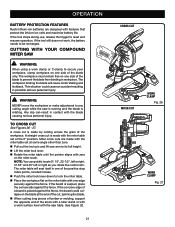
...cross cut is made with the miter table set at the 0° position. A straight cross cut is warped, place the convex side against the fence, the board could cause an accident resulting in contact with the blade causing serious personal injury. If the board is made by cutting across the...YOUR Compound MITER SAW WARNING: When using a work surface level with the saw is running and the blade is placed against the fence. OPERATION BATTERY PROTECTION FEATURES Ryobi lithium-ion batteries are made with the miter table set at some angle other than zero. Pull out the lock ...
...cross cut is made with the miter table set at the 0° position. A straight cross cut is warped, place the convex side against the fence, the board could cause an accident resulting in contact with the blade causing serious personal injury. If the board is made by cutting across the...YOUR Compound MITER SAW WARNING: When using a work surface level with the saw is running and the blade is placed against the fence. OPERATION BATTERY PROTECTION FEATURES Ryobi lithium-ion batteries are made with the miter table set at some angle other than zero. Pull out the lock ...

User Manual
Page 22
...with edge of saw blade. Grasp the stock firmly with one hand and secure it against the fence, the board could collapse on the miter scale. TO Bevel Cut See Figures 28 - 29. NOTE: ... lock knob. Place the workpiece flat on the miter table with one edge securely against the fence. See Figure 32. Align the cutting line on the workpiece with the edge of saw blade...pieces of lumber or molding, support the opposite end of a board is warped, place the convex side against the fence. If the concave edge of the stock with a roller stand or with a work clamp or a C-clamp ...
...with edge of saw blade. Grasp the stock firmly with one hand and secure it against the fence, the board could collapse on the miter scale. TO Bevel Cut See Figures 28 - 29. NOTE: ... lock knob. Place the workpiece flat on the miter table with one edge securely against the fence. See Figure 32. Align the cutting line on the workpiece with the edge of saw blade...pieces of lumber or molding, support the opposite end of a board is warped, place the convex side against the fence. If the concave edge of the stock with a roller stand or with a work clamp or a C-clamp ...

User Manual
Page 24
... LONG WORKPIECES See Figure 32. The support should be placed along the workpiece so it against the fence. See Figure 32. Align the cutting line on the workpiece with one edge securely against the fence. Long workpieces need extra supports. OPERATION Place the workpiece flat on the miter table with... surface level with the saw blade. Grasp the stock firmly with the edge of the cut is warped, place the convex side against the fence, the board could collapse on the base of the workpiece. If the concave edge of a board is placed against the...
... LONG WORKPIECES See Figure 32. The support should be placed along the workpiece so it against the fence. See Figure 32. Align the cutting line on the workpiece with one edge securely against the fence. Long workpieces need extra supports. OPERATION Place the workpiece flat on the miter table with... surface level with the saw blade. Grasp the stock firmly with the edge of the cut is warped, place the convex side against the fence, the board could collapse on the base of the workpiece. If the concave edge of a board is placed against the...
User Manual
Page 26
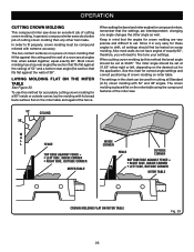
...;. See the chart for these angles to set. OPERATION cutting crown molding This compound miter saw . 52° 38° ceiling w a l l Fence inside or outside corner BOTTOM edge against the ceiling) of exactly 90°, therefore, you will need to fit properly, crown molding must be set...method the bevel angle should be tested on scrap molding. Most crown molding has a top rear angle (the section that fits flat against fence = RIGHT SIDE, INSIDE CORNER LEFT SIDE, OUTSIDE CORNER MITER Table crown molding flat on the miter table See Figure 33. The crown molding...
...;. See the chart for these angles to set. OPERATION cutting crown molding This compound miter saw . 52° 38° ceiling w a l l Fence inside or outside corner BOTTOM edge against the ceiling) of exactly 90°, therefore, you will need to fit properly, crown molding must be set...method the bevel angle should be tested on scrap molding. Most crown molding has a top rear angle (the section that fits flat against fence = RIGHT SIDE, INSIDE CORNER LEFT SIDE, OUTSIDE CORNER MITER Table crown molding flat on the miter table See Figure 33. The crown molding...

User Manual
Page 27
... side, inside corner 1. WARNING: To avoid a kickback and to avoid serious personal injury, never position the concave edge of bowed or warped material against the fence as shown in figure 34. Miter table set left 31.62° 3. When cutting warped material, always make sure it will pinch the blade near... Setting 33.85° 33.85° 33.85° 33.85° Type of Cut Left side, inside corner 1. Top edge of molding against fence 2. Miter table set right 31.62° 3. Miter table set left 31.62° 3. If the warped material is positioned the wrong way as shown...
... side, inside corner 1. WARNING: To avoid a kickback and to avoid serious personal injury, never position the concave edge of bowed or warped material against the fence as shown in figure 34. Miter table set left 31.62° 3. When cutting warped material, always make sure it will pinch the blade near... Setting 33.85° 33.85° 33.85° 33.85° Type of Cut Left side, inside corner 1. Top edge of molding against fence 2. Miter table set right 31.62° 3. Miter table set left 31.62° 3. If the warped material is positioned the wrong way as shown...
User Manual
Page 29
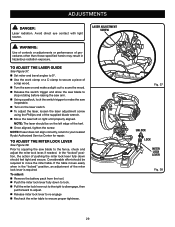
... left edge of scrap wood. Turn the saw on the left or right until properly aligned. Considerable effort should be required to the fence, check and adjust the miter lock lever, if needed. ADJUSTMENTS Danger: Laser radiation. TO ADJUST THE LASER GUIDE See Figure 37. ...right to disengage, then pull forward to adjust. Release miter lock lever to re-engage Recheck the miter table to your nearest Ryobi Authorized Service Center for repair. To adjust: Remove the battery pack from the tool. Push the miter lock lever fully down...
... left edge of scrap wood. Turn the saw on the left or right until properly aligned. Considerable effort should be required to the fence, check and adjust the miter lock lever, if needed. ADJUSTMENTS Danger: Laser radiation. TO ADJUST THE LASER GUIDE See Figure 37. ...right to disengage, then pull forward to adjust. Release miter lock lever to re-engage Recheck the miter table to your nearest Ryobi Authorized Service Center for repair. To adjust: Remove the battery pack from the tool. Push the miter lock lever fully down...
User Manual 4
Page 6
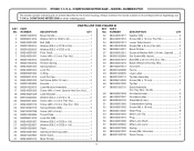
... mm, Hex Soc. Hd 1 080001020016 Tension Spring 1 40 089240001076 Blade Wrench (Hex Key, M5 1 089240001034 Spring Spacer 1 41 089100207013 Grommet 1 089240001024 Lock Pin 1 42 080001020008 Fence 1 089083001092 O-Ring 1 43 080001020905 Logo Label 1 080006014019 Lock Pin Cap 1 44 080001020710 Tip Bar Assembly 1 089240001023 Set Screw (M8 x 16 mm 2 45 080006014059 Screw (M4... 18 19 20 21 22 23 24 25 26 27 28 29 30 31 PARTS LIST FOR FIGURE B PART NUMBER DESCRIPTION QTY KEY PART NO. RYOBI 7-1/4 in . COMPOUND MITER SAW -
... mm, Hex Soc. Hd 1 080001020016 Tension Spring 1 40 089240001076 Blade Wrench (Hex Key, M5 1 089240001034 Spring Spacer 1 41 089100207013 Grommet 1 089240001024 Lock Pin 1 42 080001020008 Fence 1 089083001092 O-Ring 1 43 080001020905 Logo Label 1 080006014019 Lock Pin Cap 1 44 080001020710 Tip Bar Assembly 1 089240001023 Set Screw (M8 x 16 mm 2 45 080006014059 Screw (M4... 18 19 20 21 22 23 24 25 26 27 28 29 30 31 PARTS LIST FOR FIGURE B PART NUMBER DESCRIPTION QTY KEY PART NO. RYOBI 7-1/4 in . COMPOUND MITER SAW -


