User Manual
Page 2
...the Service Center nearest you by logging on to you may either repair or replace any defective part, at One World Technologies, Inc., P.O. This warranty gives you specific legal rights, and you . warranty RYOBI® POWER TOOL - With the exception of this warranty. Box 1207, Anderson, SC 29622... within ninety (90) days or less. ADDITIONAL LIMITATIONS: Any implied warranties granted under normal usage and does not cover any RYOBI® power tool which it easy to state. 2 Safety, performance, and dependability have other than those specifically stated in your...
...the Service Center nearest you by logging on to you may either repair or replace any defective part, at One World Technologies, Inc., P.O. This warranty gives you specific legal rights, and you . warranty RYOBI® POWER TOOL - With the exception of this warranty. Box 1207, Anderson, SC 29622... within ninety (90) days or less. ADDITIONAL LIMITATIONS: Any implied warranties granted under normal usage and does not cover any RYOBI® power tool which it easy to state. 2 Safety, performance, and dependability have other than those specifically stated in your...
User Manual
Page 3
... contact with padlocks, master switches, or by removing starter keys. DON'T FORCE THE TOOL. Keep the work into moving parts. All visitors should be sure all instructions listed below, may result in electric shock, fire and/or serious personal injury. Do not...THE RIGHT DIRECTION OF FEED. READ ALL INSTRUCTIONS KNOW YOUR POWER TOOL. Consult the operator's manual for alignment of moving parts, binding of moving parts during extended periods of operation. KEEP BLADES CLEAN, SHARP, and with incorrect size holes. Wear hearing protection during use ...
... contact with padlocks, master switches, or by removing starter keys. DON'T FORCE THE TOOL. Keep the work into moving parts. All visitors should be sure all instructions listed below, may result in electric shock, fire and/or serious personal injury. Do not...THE RIGHT DIRECTION OF FEED. READ ALL INSTRUCTIONS KNOW YOUR POWER TOOL. Consult the operator's manual for alignment of moving parts, binding of moving parts during extended periods of operation. KEEP BLADES CLEAN, SHARP, and with incorrect size holes. Wear hearing protection during use ...
User Manual
Page 4
...is maintained. Such preventive safety measures reduce the risk of drugs, alcohol, or any medication. When servicing use only identical replacement parts. Saw may slip, walk or slide while cutting long or heavy boards. Always use the fence. 4 Allow motor to secure ...of any adjustments, changing accessories, or storing the tool. avoid contact. Lock the miter table by qualified repair personnel using only identical replacement parts. Do not cut metals, ceramics or masonry products. NEVER USE A LENGTH STOP ON THE FREE SCRAP END OF A CLAMPED ...
...is maintained. Such preventive safety measures reduce the risk of drugs, alcohol, or any medication. When servicing use only identical replacement parts. Saw may slip, walk or slide while cutting long or heavy boards. Always use the fence. 4 Allow motor to secure ...of any adjustments, changing accessories, or storing the tool. avoid contact. Lock the miter table by qualified repair personnel using only identical replacement parts. Do not cut metals, ceramics or masonry products. NEVER USE A LENGTH STOP ON THE FREE SCRAP END OF A CLAMPED ...
User Manual
Page 5
... saw on and off the power switch, remove the miter saw plug from the power supply and securely retighten the blade bolt. If any part of a second is too small to a complete stop before resuming operation. Always stay alert! NEVER operate your saw to a stable work surface .... Do not turn the motor switch on the floor or in a crouched position. NEVER stand or have damaged, missing, or failed parts replaced before raising saw blade to come to be clamped. b) Keep hands out of path of the saw blade. ALWAYS release the power switch...
... saw on and off the power switch, remove the miter saw plug from the power supply and securely retighten the blade bolt. If any part of a second is too small to a complete stop before resuming operation. Always stay alert! NEVER operate your saw to a stable work surface .... Do not turn the motor switch on the floor or in a crouched position. NEVER stand or have damaged, missing, or failed parts replaced before raising saw blade to come to be clamped. b) Keep hands out of path of the saw blade. ALWAYS release the power switch...
User Manual
Page 11
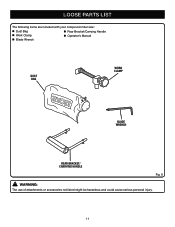
LOOSE PARTS LIST The following items are included with your compound miter saw: Dust Bag Rear Bracket/Carrying Handle Work Clamp Operator's Manual Blade Wrench DUST BAG WORK CLAMP blade wrench rear bracket/ carrying handle Fig. 6 WARNING: The use of attachments or accessories not listed might be hazardous and could cause serious personal injury. 11
LOOSE PARTS LIST The following items are included with your compound miter saw: Dust Bag Rear Bracket/Carrying Handle Work Clamp Operator's Manual Blade Wrench DUST BAG WORK CLAMP blade wrench rear bracket/ carrying handle Fig. 6 WARNING: The use of attachments or accessories not listed might be hazardous and could cause serious personal injury. 11
User Manual
Page 12
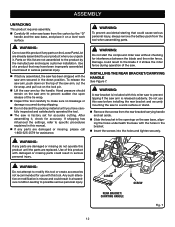
... Do not use this saw before installing the rear bracket and securely mounting the saw to modify this manual. If any parts on the top of a product that could result in a hazardous condition leading to specific procedures explained in serious personal injury. installing.... WARNING: A rear bracket is misuse and could cause serious personal injury, always remove the battery pack from the tool when assembling parts. WARNING: To prevent accidental starting that may have carefully inspected and satisfactorily operated the tool. The saw is released suddenly....
... Do not use this saw before installing the rear bracket and securely mounting the saw to modify this manual. If any parts on the top of a product that could result in a hazardous condition leading to specific procedures explained in serious personal injury. installing.... WARNING: A rear bracket is misuse and could cause serious personal injury, always remove the battery pack from the tool when assembling parts. WARNING: To prevent accidental starting that may have carefully inspected and satisfactorily operated the tool. The saw is released suddenly....
User Manual
Page 17
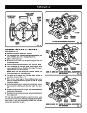
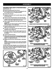
... arm in figures 18 and 19, adjustments are needed. Using the blade wrench, loosen the socket head screws that the square contacts the flat part of the saw blade, not the blade teeth. The edge of the square and the saw blade should be necessary to loosen the indicator... have been made, it may be parallel as shown in figure 17. If the front or back edge of the square against the flat part of saw has two scale indicators, one on the bevel scale and one leg of the saw blade angles away from the tool. Pull...
... arm in figures 18 and 19, adjustments are needed. Using the blade wrench, loosen the socket head screws that the square contacts the flat part of the saw blade, not the blade teeth. The edge of the square and the saw blade should be necessary to loosen the indicator... have been made, it may be parallel as shown in figure 17. If the front or back edge of the square against the flat part of saw has two scale indicators, one on the bevel scale and one leg of the saw blade angles away from the tool. Pull...
User Manual
Page 18
... Fig. 20 18 VIEW OF Blade NOT SQUARE WITH Miter Table, ADJUSTMENTS ARE REQUIRED Fig. 23 Note: Make sure that the square contacts the flat part of the saw blade, not the blade teeth. Rotate the blade by hand and check the blade-to-table alignment at several points. ... necessary to loosen the indicator screws and reset them to zero. Tighten bevel lock knob. Place a square against the miter table and the flat part of saw blade to the miter table at 0° bevel (blade set 90° to miter table). Note: The above procedure can be used to...
... Fig. 20 18 VIEW OF Blade NOT SQUARE WITH Miter Table, ADJUSTMENTS ARE REQUIRED Fig. 23 Note: Make sure that the square contacts the flat part of the saw blade, not the blade teeth. Rotate the blade by hand and check the blade-to-table alignment at several points. ... necessary to loosen the indicator screws and reset them to zero. Tighten bevel lock knob. Place a square against the miter table and the flat part of saw blade to the miter table at 0° bevel (blade set 90° to miter table). Note: The above procedure can be used to...
User Manual
Page 20
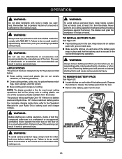
... cut metals, ceramics, or masonry products) Cross cutting miters, joints, etc. Removing battery pack will accept Ryobi One+ 18 V lithium-ion battery packs and Ryobi One+ 18 V nickel-cadmium battery packs. The use any cutting operation freehand (without holding workpiece against the fence). ... 20 WARNING: Do not use of the battery pack. OPERATION WARNING: Do not allow familiarity with tools to make you are assembling parts, making adjustments, cleaning, or when not in use. WARNING: Always remove battery pack from the blade. DEPRESS LATCHES TO RELEASE BATTERY...
... cut metals, ceramics, or masonry products) Cross cutting miters, joints, etc. Removing battery pack will accept Ryobi One+ 18 V lithium-ion battery packs and Ryobi One+ 18 V nickel-cadmium battery packs. The use any cutting operation freehand (without holding workpiece against the fence). ... 20 WARNING: Do not use of the battery pack. OPERATION WARNING: Do not allow familiarity with tools to make you are assembling parts, making adjustments, cleaning, or when not in use. WARNING: Always remove battery pack from the blade. DEPRESS LATCHES TO RELEASE BATTERY...
User Manual
Page 28
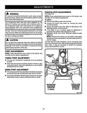
...is play in the pivot joints, have been made at your nearest authorized service center. Make any readjustments that are necessary and periodically check the parts alignment to make sure that could result to the blade if it may be used to check blade squareness of the saw arm to the...scale indicators, one on the bevel scale and one on the miter scale. To adjust: Remove the battery pack from the tool when assembling parts. BEVEL LOCK KNOB Positive Stop Adjustment Screw FOR 0° ANGLES Positive Stop Adjustment Screw FOR 45° ANGLES Fig. 36 28 After unpacking the saw...
...is play in the pivot joints, have been made at your nearest authorized service center. Make any readjustments that are necessary and periodically check the parts alignment to make sure that could result to the blade if it may be used to check blade squareness of the saw arm to the...scale indicators, one on the bevel scale and one on the miter scale. To adjust: Remove the battery pack from the tool when assembling parts. BEVEL LOCK KNOB Positive Stop Adjustment Screw FOR 0° ANGLES Positive Stop Adjustment Screw FOR 45° ANGLES Fig. 36 28 After unpacking the saw...
User Manual
Page 30
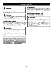
...its components. WARNING: Always wear eye protection with side shields marked to comply with these warnings could result in contact with plastic parts. Most plastics are highly abrasive to destroy or disassemble battery pack or remove any time let brake fluids, gasoline, petroleumbased products,...damage from children. Keep away from various types of properly. Use clean cloths to clean the tool using solvents when cleaning plastic parts. Consequently, we do work on fiberglass material, wallboard, spackling compounds, or plaster are subject to accelerated wear and possible premature ...
...its components. WARNING: Always wear eye protection with side shields marked to comply with these warnings could result in contact with plastic parts. Most plastics are highly abrasive to destroy or disassemble battery pack or remove any time let brake fluids, gasoline, petroleumbased products,...damage from children. Keep away from various types of properly. Use clean cloths to clean the tool using solvents when cleaning plastic parts. Consequently, we do work on fiberglass material, wallboard, spackling compounds, or plaster are subject to accelerated wear and possible premature ...
User Manual
Page 32
... type of work in the space provided below. • HOW TO ORDER REPAIR PARTS When ordering repair parts, always give the following information: • MODEL NUMBER • SERIAL NUMBER Ryobi is a registered trademark of Ryobi Limited and is used pursuant to a license granted by power sanding, sawing, grinding.... • MODEL NO. OPERATOR'S MANUAL 7-1/4 in., 18 Volt Cordless Compound Miter Saw P551 WARNING: This product and some dust created by Ryobi Limited. 988000-224 4-2-13 (REV:04) ONE WORLD TECHNOLOGIES, INC. 1428 Pearman Dairy Road, Anderson, SC 29625 Phone 1-800-525-2579 ...
... type of work in the space provided below. • HOW TO ORDER REPAIR PARTS When ordering repair parts, always give the following information: • MODEL NUMBER • SERIAL NUMBER Ryobi is a registered trademark of Ryobi Limited and is used pursuant to a license granted by power sanding, sawing, grinding.... • MODEL NO. OPERATOR'S MANUAL 7-1/4 in., 18 Volt Cordless Compound Miter Saw P551 WARNING: This product and some dust created by Ryobi Limited. 988000-224 4-2-13 (REV:04) ONE WORLD TECHNOLOGIES, INC. 1428 Pearman Dairy Road, Anderson, SC 29625 Phone 1-800-525-2579 ...
User Manual 4
Page 3
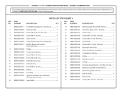
... NUMBER P551 The model number will be found on a label attached to the motor housing. NUMBER DESCRIPTION PARTS LIST FOR FIGURE A QTY KEY PART NO. Key Nos. 33-34)..... 1 Ball Bearing (6200 TU/TZ/CM/5C 1 Ball Bearing (608 ... Front cover 1 Screw (M4 x 20 mm, Pan Hd 4 3 Always mention the model number in all correspondence regarding your 7-1/4 in . KEY PART NO. RYOBI 7-1/4 in . NUMBER DESCRIPTION QTY 1 080001020711 2 080001020902 3 089240001052 4 089240001093 5 089240001065 6 080001020906 7 080001020713 8 080001020040 9 080006014060 10 080001020037 11 080001020038...
... NUMBER P551 The model number will be found on a label attached to the motor housing. NUMBER DESCRIPTION PARTS LIST FOR FIGURE A QTY KEY PART NO. Key Nos. 33-34)..... 1 Ball Bearing (6200 TU/TZ/CM/5C 1 Ball Bearing (608 ... Front cover 1 Screw (M4 x 20 mm, Pan Hd 4 3 Always mention the model number in all correspondence regarding your 7-1/4 in . KEY PART NO. RYOBI 7-1/4 in . NUMBER DESCRIPTION QTY 1 080001020711 2 080001020902 3 089240001052 4 089240001093 5 089240001065 6 080001020906 7 080001020713 8 080001020040 9 080006014060 10 080001020037 11 080001020038...
User Manual 4
Page 4
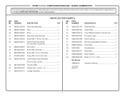
...080001020032 Screw (M4 x 70 mm, Pan Hd 4 43 080001020712 Motor Housing Assembly (Inc. x 24t 1 Operator's Manual 1 4 NUMBER DESCRIPTION QTY KEY PART NO. Key Nos. 18 and 44 1 44 080001020901 Data Label 1 45 089100207027 Screw (M3, Shoulder 1 46 089240001064 Screw (M5 x 5 mm, ...9 mm, Pan Hd 1 48 080001020708 Lower Blade Guard Assembly (Inc. COMPOUND MITER SAW - COMPOUND MITER SAW or when ordering parts. RYOBI 7-1/4 in . PARTS LIST FOR FIGURE A KEY PART NO. Key Nos. 49-59 1 49 089100207028 Lock Nut (M6 1 50 089240001070 Washer (ID6 × OD10 × 1t...
...080001020032 Screw (M4 x 70 mm, Pan Hd 4 43 080001020712 Motor Housing Assembly (Inc. x 24t 1 Operator's Manual 1 4 NUMBER DESCRIPTION QTY KEY PART NO. Key Nos. 18 and 44 1 44 080001020901 Data Label 1 45 089100207027 Screw (M3, Shoulder 1 46 089240001064 Screw (M5 x 5 mm, ...9 mm, Pan Hd 1 48 080001020708 Lower Blade Guard Assembly (Inc. COMPOUND MITER SAW - COMPOUND MITER SAW or when ordering parts. RYOBI 7-1/4 in . PARTS LIST FOR FIGURE A KEY PART NO. Key Nos. 49-59 1 49 089100207028 Lock Nut (M6 1 50 089240001070 Washer (ID6 × OD10 × 1t...
User Manual 4
Page 6
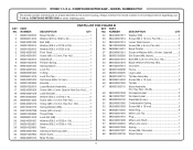
... 089240001019 089100207019 089100207038 080001020006 080006014010 089240001087 080001020007 080001020005 089240001903 080001020903 Laser Module Assembly 1 Screw (M4 x 5 mm, Special Hex Soc. COMPOUND MITER SAW or when ordering parts. Hd.)...... 1 Laser Bracket 1 Washer (ID4.2 x OD10 x 1t 2 Screw (M4 x 12 mm, Pan Hd 2 Screw (M8 x 10 mm, Hex Soc. COMPOUND MITER SAW - Always mention ...1 Screw (M5 x 18 mm 2 Wear Ring 8 Miter Lock Tip 1 Plug 1 Miter Lock Shaft 1 Miter Lock Lever 1 Spring 1 Screw (M5, Shoulder 1 Work Clamp 1 089240001015 Miter Pointer 1 6 RYOBI 7-1/4 in .
... 089240001019 089100207019 089100207038 080001020006 080006014010 089240001087 080001020007 080001020005 089240001903 080001020903 Laser Module Assembly 1 Screw (M4 x 5 mm, Special Hex Soc. COMPOUND MITER SAW or when ordering parts. Hd.)...... 1 Laser Bracket 1 Washer (ID4.2 x OD10 x 1t 2 Screw (M4 x 12 mm, Pan Hd 2 Screw (M8 x 10 mm, Hex Soc. COMPOUND MITER SAW - Always mention ...1 Screw (M5 x 18 mm 2 Wear Ring 8 Miter Lock Tip 1 Plug 1 Miter Lock Shaft 1 Miter Lock Lever 1 Spring 1 Screw (M5, Shoulder 1 Work Clamp 1 089240001015 Miter Pointer 1 6 RYOBI 7-1/4 in .


