
English Manual
Page 1
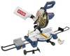
OPERATOR'S MANUAL 10 in. WARNING: To reduce the risk of operation, and operator safety. Thank you years of rugged, trouble-free performance. SAVE THIS MANUAL FOR FUTURE REFERENCE Double Insulated Your miter saw has been engineered and manufactured to our high standard for purchase. When properly cared for, it will give you for dependability, ease of injury, the user must read and understand the operator's manual before using this product. Compound Miter Saw TS1355LA -
OPERATOR'S MANUAL 10 in. WARNING: To reduce the risk of operation, and operator safety. Thank you years of rugged, trouble-free performance. SAVE THIS MANUAL FOR FUTURE REFERENCE Double Insulated Your miter saw has been engineered and manufactured to our high standard for purchase. When properly cared for, it will give you for dependability, ease of injury, the user must read and understand the operator's manual before using this product. Compound Miter Saw TS1355LA -
English Manual
Page 4
...plug in any solvents to be installed on the miter table and position it still does not fit, contact a qualified electrician to power supply. Saw may create a hazard or cause product damage. USE ONLY RECOMMENDED ACCESSORIES listed in . BEFORE MAKING A CUT, BE SURE... lock levers. Make sure blade is wider than one way. The maximum blade capacity of the workpiece in blade cutting path with saw from lumber before cutting. NEVER TOUCH BLADE or other ). Instructions for any operation. Normal sparking of accessories are used together...
...plug in any solvents to be installed on the miter table and position it still does not fit, contact a qualified electrician to power supply. Saw may create a hazard or cause product damage. USE ONLY RECOMMENDED ACCESSORIES listed in . BEFORE MAKING A CUT, BE SURE... lock levers. Make sure blade is wider than one way. The maximum blade capacity of the workpiece in blade cutting path with saw from lumber before cutting. NEVER TOUCH BLADE or other ). Instructions for any operation. Normal sparking of accessories are used together...
English Manual
Page 5
...too small to be replaced only by the manufacturer or by the carrying handle. AVOID direct eye exposure when using the saw blade to stop . e) Never reach around saw blade. ALWAYS secure this tool, loan them frequently and use to avoid serious personal injury. SAVE THESE INSTRUCTIONS. Refer... by an authorized service center to avoid risk. MAKE SURE THE WORK AREA HAS AMPLE LIGHTING to pick up a workpiece, a piece of saw blade. Keep hands clear of the cutting area. NEVER reach behind, under, or within three inches of the blade and its cutting path ...
...too small to be replaced only by the manufacturer or by the carrying handle. AVOID direct eye exposure when using the saw blade to stop . e) Never reach around saw blade. ALWAYS secure this tool, loan them frequently and use to avoid serious personal injury. SAVE THESE INSTRUCTIONS. Refer... by an authorized service center to avoid risk. MAKE SURE THE WORK AREA HAS AMPLE LIGHTING to pick up a workpiece, a piece of saw blade. Keep hands clear of the cutting area. NEVER reach behind, under, or within three inches of the blade and its cutting path ...
English Manual
Page 9
...minute. Resaw A cutting operation to reduce the thickness of a workpiece usually caused by a spinning object in a workpiece that has hardened. Through Sawing Any cutting operation where the blade extends completely through cut made across the grain or the width of turns completed by the workpiece being dropped... keep the operator's hands well away from the cutterhead. Non-Through Cuts Any cutting operation where the blade does not extend completely through the saw during any angle other than 90° to the table surface. A push stick (not a push block) should be or has been...
...minute. Resaw A cutting operation to reduce the thickness of a workpiece usually caused by a spinning object in a workpiece that has hardened. Through Sawing Any cutting operation where the blade extends completely through cut made across the grain or the width of turns completed by the workpiece being dropped... keep the operator's hands well away from the cutterhead. Non-Through Cuts Any cutting operation where the blade does not extend completely through the saw during any angle other than 90° to the table surface. A push stick (not a push block) should be or has been...
English Manual
Page 11
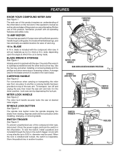
..., changing, or removing blade. To lock the switch, install a padlock (not included) through the hole in . FEATURES KNOW YOUR COMPOUND MITER SAW See Figure 1. A storage area for ease of servicing. 10 in this product requires an understanding of the information on top of the compound miter...or removing blade and the phillips end when removing or loosening screws. A lock with all operating features and safety rules. 15 AMP MOTOR The saw arm by depressing the lock pin. BLADE A 10 in the switch trigger. One end of the project you are attempting. SWITCH TRIGGER See ...
..., changing, or removing blade. To lock the switch, install a padlock (not included) through the hole in . FEATURES KNOW YOUR COMPOUND MITER SAW See Figure 1. A storage area for ease of servicing. 10 in this product requires an understanding of the information on top of the compound miter...or removing blade and the phillips end when removing or loosening screws. A lock with all operating features and safety rules. 15 AMP MOTOR The saw arm by depressing the lock pin. BLADE A 10 in the switch trigger. One end of the project you are attempting. SWITCH TRIGGER See ...
English Manual
Page 12
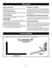
... Fig. 5 The 22-1/2° and 45° positive stops have been provided at desired bevel angles. The left and right side of the saw at 0°, 15°, 22-1/2°, 30°, and 45°. When used properly, the laser guide makes accurate, precision cutting simple ...For more accurate cuts, a laser guide is released. Turn the handle adjusting knob clockwise to loosen the rotating handle before attempting to provide different saw . TOOLS NEEDED The following tools (not included) are needed for clearance of the miter table. ROTATING "D" HANDLE The rotating "D" handle can be...
... Fig. 5 The 22-1/2° and 45° positive stops have been provided at desired bevel angles. The left and right side of the saw at 0°, 15°, 22-1/2°, 30°, and 45°. When used properly, the laser guide makes accurate, precision cutting simple ...For more accurate cuts, a laser guide is released. Turn the handle adjusting knob clockwise to loosen the rotating handle before attempting to provide different saw . TOOLS NEEDED The following tools (not included) are needed for clearance of the miter table. ROTATING "D" HANDLE The rotating "D" handle can be...
English Manual
Page 13
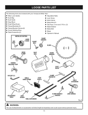
LOOSE PARTS LIST The following items are included with your Compound Miter Saw: Miter Lock Handle Adjustable Table Dust Bag Dust Guide Stop Block Small Wing Screw Clamp Brackets (2) Clamp ...
LOOSE PARTS LIST The following items are included with your Compound Miter Saw: Miter Lock Handle Adjustable Table Dust Bag Dust Guide Stop Block Small Wing Screw Clamp Brackets (2) Clamp ...
English Manual
Page 14
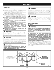
...this product or create accessories not recommended for accurate cutting. WARNING: Always make sure that no breakage or damage occurred during use with the saw arm secured in the down on the "D" handle, cut the tie-wrap, and pull out on a level work surface before operating.... NOTE: This tool is securely mounted to a stable work surface. To release the saw to a workbench or an approved workstand. MOUNTING HOLES See Figure 7. WARNING: Do not attempt to a work surface. Four bolt holes have carefully...
...this product or create accessories not recommended for accurate cutting. WARNING: Always make sure that no breakage or damage occurred during use with the saw arm secured in the down on the "D" handle, cut the tie-wrap, and pull out on a level work surface before operating.... NOTE: This tool is securely mounted to a stable work surface. To release the saw to a workbench or an approved workstand. MOUNTING HOLES See Figure 7. WARNING: Do not attempt to a work surface. Four bolt holes have carefully...
English Manual
Page 15
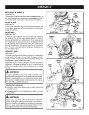
... for use a C-clamp instead of the blade guard assembly. This will eliminate the possibility of the miter lock handle into the threaded hole in the saw . ASSEMBLY MITER LOCK HANDLE See Figure 8. It also prevents the workpiece from exhaust port. This is facing down. To install the work clamp to ...secure the workpiece prior to heed this miter saw blade and workpiece kicking up. To install the miter lock handle, place the threaded stud on the same side as needed. Turn the guide so...
... for use a C-clamp instead of the blade guard assembly. This will eliminate the possibility of the miter lock handle into the threaded hole in the saw . ASSEMBLY MITER LOCK HANDLE See Figure 8. It also prevents the workpiece from exhaust port. This is facing down. To install the work clamp to ...secure the workpiece prior to heed this miter saw blade and workpiece kicking up. To install the miter lock handle, place the threaded stud on the same side as needed. Turn the guide so...
English Manual
Page 16
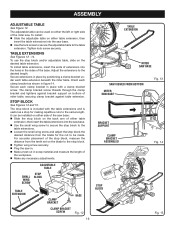
... adjustable table can be made. Tighten lock screw securely. To use the stop block and/or adjustable table, slide on bottom of the miter saw base. Use the small wing screw to secure the stop block to the table extensions. � Loosen the small wing screw... extension. ADJUSTABLE TABLE SMALL WING SCREW STOP BLOCK TABLE EXTENSION CLAMP BRACKET BASE CLAMP BRACKET SCREW Fig. 12 16 TABLE EXTENSION MITER SAW BASE SAW VIEWED FROM BOTTOM MITER SAW BASE Fig. 13 BRACKET SUPPORT CLAMP BRACKET ASSEMBLED Fig. 14 STOP BLOCK Fig. 15 TABLE EXTENSIONS See Figures 12 - 14....
... adjustable table can be made. Tighten lock screw securely. To use the stop block and/or adjustable table, slide on bottom of the miter saw base. Use the small wing screw to secure the stop block to the table extensions. � Loosen the small wing screw... extension. ADJUSTABLE TABLE SMALL WING SCREW STOP BLOCK TABLE EXTENSION CLAMP BRACKET BASE CLAMP BRACKET SCREW Fig. 12 16 TABLE EXTENSION MITER SAW BASE SAW VIEWED FROM BOTTOM MITER SAW BASE Fig. 13 BRACKET SUPPORT CLAMP BRACKET ASSEMBLED Fig. 14 STOP BLOCK Fig. 15 TABLE EXTENSIONS See Figures 12 - 14....

English Manual
Page 17
...will come in contact with the blade teeth and the arrow printed on the spindle. The blade teeth point downward at the front of the saw. SPINDLE LOCK BUTTON NOTE: BEFORE USE, REPLACE SCREW AND TIGHTEN SECURELY TO PREVENT GUARD MOVEMENT SCREW OUTER BLADE WASHER Fig. 16 BLADE BOLT... BLADE WASHER BLADE BOLT COVER BLADE CAUTION: Always install the blade with the blade guards, while thicker blades will not tighten properly. Fit saw as shown in figure 17. Replace outer blade washer (or laser guide). The direction of blade rotation is also stamped with the flats...
...will come in contact with the blade teeth and the arrow printed on the spindle. The blade teeth point downward at the front of the saw. SPINDLE LOCK BUTTON NOTE: BEFORE USE, REPLACE SCREW AND TIGHTEN SECURELY TO PREVENT GUARD MOVEMENT SCREW OUTER BLADE WASHER Fig. 16 BLADE BOLT... BLADE WASHER BLADE BOLT COVER BLADE CAUTION: Always install the blade with the blade guards, while thicker blades will not tighten properly. Fit saw as shown in figure 17. Replace outer blade washer (or laser guide). The direction of blade rotation is also stamped with the flats...

English Manual
Page 18
...lowered toward the workpiece, the broken line will become familiar with using the laser guide. MOUNTING THE LASER GUIDE See Figure 18. Unplug the saw into power source. NOTE: The hex bolt has left edge of material. 18 BROKEN RED LINE Fig. 19 Tighten screw securely. Avoid direct eye contact... with the blade at the same time, and will appear as a broken line on the workpiece when the blade assembly is in place before reconnecting saw . Remove hex bolt, washer, and outer blade washer. The red laser line will assist you see your mark on the work surface when ...
...lowered toward the workpiece, the broken line will become familiar with using the laser guide. MOUNTING THE LASER GUIDE See Figure 18. Unplug the saw into power source. NOTE: The hex bolt has left edge of material. 18 BROKEN RED LINE Fig. 19 Tighten screw securely. Avoid direct eye contact... with the blade at the same time, and will appear as a broken line on the workpiece when the blade assembly is in place before reconnecting saw . Remove hex bolt, washer, and outer blade washer. The red laser line will assist you see your mark on the work surface when ...
English Manual
Page 19
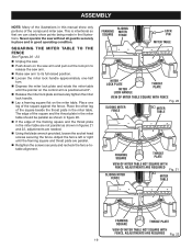
...THE MITER TABLE TO THE FENCE See Figures 20 - 23. Unplug the saw. Push down on the miter table. Place the other leg of the ... tighten the miter lock handle. Lay a framing square flat on the saw arm and pull out the lock pin to release the saw arm. Raise saw without all guards securely in place and in good operating condition. Never operate the...the pointer on the control arm is intentional so that we can clearly show only portions of the compound miter saw. The edge of the square and the throat plate in the miter table should be parallel as shown in...
...THE MITER TABLE TO THE FENCE See Figures 20 - 23. Unplug the saw. Push down on the miter table. Place the other leg of the ... tighten the miter lock handle. Lay a framing square flat on the saw arm and pull out the lock pin to release the saw arm. Raise saw without all guards securely in place and in good operating condition. Never operate the...the pointer on the control arm is intentional so that we can clearly show only portions of the compound miter saw. The edge of the square and the throat plate in the miter table should be parallel as shown in...
English Manual
Page 20
... After squaring adjustments have been made, it may be parallel as shown in figure 24. If the front or back edge of the saw blade angles away from the square as shown in transport position. Loosen the miter lock handle approximately one-half turn. Depress ...the miter lock plate and rotate the miter table until the saw blade is positioned at 0°. Release the miter lock plate and securely tighten the miter lock handle. Lay a framing square flat...
... After squaring adjustments have been made, it may be parallel as shown in figure 24. If the front or back edge of the saw blade angles away from the square as shown in transport position. Loosen the miter lock handle approximately one-half turn. Depress ...the miter lock plate and rotate the miter table until the saw blade is positioned at 0°. Release the miter lock plate and securely tighten the miter lock handle. Lay a framing square flat...
English Manual
Page 21
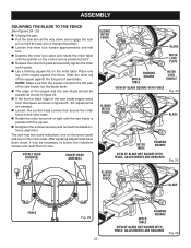
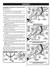
.... Loosen the lock nut securing positive stop adjustment screw. Next, retighten lock nut securing the positive stop adjustment screw to bring saw blade into alignment with the square. After squaring adjustments have been made, it may be necessary to loosen the indicator screws and reset them...ASSEMBLY SQUARING THE BLADE TO THE MITER TABLE See Figures 28 - 30. Unplug the saw. Pull the saw arm all the way down and engage the lock pin to hold the saw arm in transport position. Loosen the miter lock handle approximately one on the control arm...
.... Loosen the lock nut securing positive stop adjustment screw. Next, retighten lock nut securing the positive stop adjustment screw to bring saw blade into alignment with the square. After squaring adjustments have been made, it may be necessary to loosen the indicator screws and reset them...ASSEMBLY SQUARING THE BLADE TO THE MITER TABLE See Figures 28 - 30. Unplug the saw. Pull the saw arm all the way down and engage the lock pin to hold the saw arm in transport position. Loosen the miter lock handle approximately one on the control arm...
English Manual
Page 22
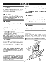
... not allow familiarity with tools to make a cut. WARNING: Do not use any cutting angle while the saw arm to inflict serious injury. A straight cross cut is sufficient to its full height. WARNING: To avoid...at least 3 in serious personal injury. Never perform any cutting operation, clamp or bolt the compound miter saw on one side of a second is made with the miter table set at the 0° position. ... from binding in serious personal injury. from the Ryobi dealer. This situation could grab the workpiece if it slips or twists. 22 WORK CLAMP Fig. 31...
... not allow familiarity with tools to make a cut. WARNING: Do not use any cutting angle while the saw arm to inflict serious injury. A straight cross cut is sufficient to its full height. WARNING: To avoid...at least 3 in serious personal injury. Never perform any cutting operation, clamp or bolt the compound miter saw on one side of a second is made with the miter table set at the 0° position. ... from binding in serious personal injury. from the Ryobi dealer. This situation could grab the workpiece if it slips or twists. 22 WORK CLAMP Fig. 31...
English Manual
Page 23
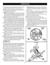
...no problems will seat itself in one edge securely against the fence. A straight bevel cut . Loosen the bevel lock knob and move the saw blade. Grasp the stock firmly with the blade angled to the left or right by cutting across the grain of workpiece. Rotate the miter...lock handle securely. Adjustments of the cutting operation just to its full height. Loosen the miter lock handle. If the concave edge of saw arm to the left to the desired bevel angle. Bevel angles can quickly locate 0°, 22-1/2° left or right, and 45° ...
...no problems will seat itself in one edge securely against the fence. A straight bevel cut . Loosen the bevel lock knob and move the saw blade. Grasp the stock firmly with the blade angled to the left or right by cutting across the grain of workpiece. Rotate the miter...lock handle securely. Adjustments of the cutting operation just to its full height. Loosen the miter lock handle. If the concave edge of saw arm to the left to the desired bevel angle. Bevel angles can quickly locate 0°, 22-1/2° left or right, and 45° ...
English Manual
Page 24
... the miter lock plate as you change the effect of the miter setting. Allow several settings to obtain the desired cut prior to tilting the saw blade. Grasp the stock firmly with one of the positive stop rotating before removing the workpiece from 0° to the correct bevel ... desired position, and retighten the fence screw. The 45° triangle on the miter table must be rotated to the correct angle and the saw blade to stop notches, located in scrap material. 24 Make a test cut in miter table frame. Tighten the miter lock handle securely. ...
... the miter lock plate as you change the effect of the miter setting. Allow several settings to obtain the desired cut prior to tilting the saw blade. Grasp the stock firmly with one of the positive stop rotating before removing the workpiece from 0° to the correct bevel ... desired position, and retighten the fence screw. The 45° triangle on the miter table must be rotated to the correct angle and the saw blade to stop notches, located in scrap material. 24 Make a test cut in miter table frame. Tighten the miter lock handle securely. ...
English Manual
Page 25
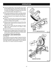
... before removing the workpiece from turning before raising the blade out of the stock with a roller stand or with a work surface level with the saw and work table during the cutting operation. TO SUPPORT LONG WORKPIECES See Figure 36. See Figures 40 - 41. When cutting long pieces...convex side against the fence. Use the optional work clamp or a C-clamp to secure the workpiece when possible. Before turning on the saw handle firmly then squeeze the switch trigger. OPERATION Place the workpiece flat on the miter table with one hand and secure it does not...
... before removing the workpiece from turning before raising the blade out of the stock with a roller stand or with a work surface level with the saw and work table during the cutting operation. TO SUPPORT LONG WORKPIECES See Figure 36. See Figures 40 - 41. When cutting long pieces...convex side against the fence. Use the optional work clamp or a C-clamp to secure the workpiece when possible. Before turning on the saw handle firmly then squeeze the switch trigger. OPERATION Place the workpiece flat on the miter table with one hand and secure it does not...
English Manual
Page 27
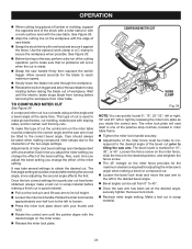
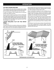
....85°. Keep in the chart can be tested on page 28 for the application. OPERATION CUTTING CROWN MOLDING This compound miter saw does an excellent job of the miter saw. 52° 38° CEILING W A L L FENCE INSIDE CORNER TOP EDGE AGAINST FENCE = LEFT SIDE, INSIDE CORNER RIGHT ... flat on the miter table using the compound features of cutting crown molding. The two contact surfaces on miter table. In general, compound miter saws do not have angles of crown molding on a piece of crown molding that , when added together, equal exactly 90°. Most crown molding...
....85°. Keep in the chart can be tested on page 28 for the application. OPERATION CUTTING CROWN MOLDING This compound miter saw does an excellent job of the miter saw. 52° 38° CEILING W A L L FENCE INSIDE CORNER TOP EDGE AGAINST FENCE = LEFT SIDE, INSIDE CORNER RIGHT ... flat on the miter table using the compound features of cutting crown molding. The two contact surfaces on miter table. In general, compound miter saws do not have angles of crown molding on a piece of crown molding that , when added together, equal exactly 90°. Most crown molding...


