Operation Manual
Page 4
... end of any reason. To reduce the risk of electric shock, this manual or addendums. Use of personal injury. If it firmly against the fence as a backstop. Never use blade washers or blade bolts that are not listed may create a hazard or cause product damage. USE ...damaged. POLARIZED PLUGS. SPECIFIC SAFETY RULES FIRMLY CLAMP OR BOLT your saw or workpiece before starting cut. NEVER cut on the miter table and position it still does not fit, contact a qualified electrician to clean tool. STAY ALERT AND EXERCISE CONTROL. Allow motor to a ...
... end of any reason. To reduce the risk of electric shock, this manual or addendums. Use of personal injury. If it firmly against the fence as a backstop. Never use blade washers or blade bolts that are not listed may create a hazard or cause product damage. USE ...damaged. POLARIZED PLUGS. SPECIFIC SAFETY RULES FIRMLY CLAMP OR BOLT your saw or workpiece before starting cut. NEVER cut on the miter table and position it still does not fit, contact a qualified electrician to clean tool. STAY ALERT AND EXERCISE CONTROL. Allow motor to a ...
Operation Manual
Page 9
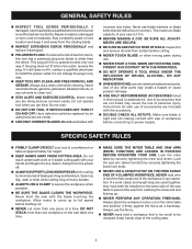
...nominal lumber sizes 2 x 6 Cutting Capacity with Miter at 45°/Bevel 45°: Maximum nominal lumber sizes 2 x 4 UPPER BLADE GUARD "D" HANDLE/ CARRYING HANDLE DUST BAG BLADE WRENCH BEVEL LOCK KNOB MITER FENCE MITER TABLE BASE SWITCH TRIGGER LOWER BLADE GUARD THROAT PLATE... "NO HANDS ZONE" BOUNDARY LINE "NO HANDS ZONE" LABEL MITER SCALE WORK CLAMP 9 CONTROL ARM MITER LOCK HANDLE Fig. 1 FEATURES PRODUCT SPECIFICATIONS Blade Arbor 5/8 ...
...nominal lumber sizes 2 x 6 Cutting Capacity with Miter at 45°/Bevel 45°: Maximum nominal lumber sizes 2 x 4 UPPER BLADE GUARD "D" HANDLE/ CARRYING HANDLE DUST BAG BLADE WRENCH BEVEL LOCK KNOB MITER FENCE MITER TABLE BASE SWITCH TRIGGER LOWER BLADE GUARD THROAT PLATE... "NO HANDS ZONE" BOUNDARY LINE "NO HANDS ZONE" LABEL MITER SCALE WORK CLAMP 9 CONTROL ARM MITER LOCK HANDLE Fig. 1 FEATURES PRODUCT SPECIFICATIONS Blade Arbor 5/8 ...
Operation Manual
Page 10
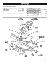
...One end of the wrench is a phillips screwdriver and the other end is also larger providing additional support. 10 LOCK PIN "D" HANDLE/ CARRYING HANDLE MITER LOCK HANDLE SAW ARM LOCKED IN DOWN POSITION Fig. 2 SPINDLE LOCK BUTTON SWITCH TRIGGER SWITCH TRIGGER Fig. 3 PADLOCK Fig. 4 ELECTRIC BRAKE An ...and unplug the saw, then lower the saw arm. When used properly, the laser guide makes accurate, precision cutting simple and easy. MITER FENCE The miter fence on each side of the project you are for ease of this operator's manual as well as a knowledge of the saw arm and ...
...One end of the wrench is a phillips screwdriver and the other end is also larger providing additional support. 10 LOCK PIN "D" HANDLE/ CARRYING HANDLE MITER LOCK HANDLE SAW ARM LOCKED IN DOWN POSITION Fig. 2 SPINDLE LOCK BUTTON SWITCH TRIGGER SWITCH TRIGGER Fig. 3 PADLOCK Fig. 4 ELECTRIC BRAKE An ...and unplug the saw, then lower the saw arm. When used properly, the laser guide makes accurate, precision cutting simple and easy. MITER FENCE The miter fence on each side of the project you are for ease of this operator's manual as well as a knowledge of the saw arm and ...
Operation Manual
Page 13
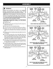
... procedures explained in a hazardous condition leading to modify this tool or create accessories not recommended for interference between the blade and the miter fence. WARNING: Do not attempt to possible serious personal injury. Any such alteration or modification is misuse and could result in this tool...the saw arm, push down position. Hand pressure should be bolted securely using 3/8 in serious personal injury. After assembling it strikes the miter fence during shipping. Do not discard the packing material until you unpack it on the lock pin. Lift the saw ...
... procedures explained in a hazardous condition leading to modify this tool or create accessories not recommended for interference between the blade and the miter fence. WARNING: Do not attempt to possible serious personal injury. Any such alteration or modification is misuse and could result in this tool...the saw arm, push down position. Hand pressure should be bolted securely using 3/8 in serious personal injury. After assembling it strikes the miter fence during shipping. Do not discard the packing material until you unpack it on the lock pin. Lift the saw ...
Operation Manual
Page 17
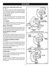
... screws securely and recheck the fence-totable alignment. FRAMING SQUARE MITER FENCE MITER TABLE SCALE INDICATOR THROAT PLATE MITER LOCK HANDLE VIEW OF MITER TABLE SQUARE WITH FENCE Fig. 15 FRAMING MITER SQUARE FENCE MITER TABLE SCALE INDICATOR THROAT PLATE MITER LOCK HANDLE VIEW OF MITER TABLE NOT SQUARE WITH FENCE, ADJUSTMENTS ARE REQUIRED Fig. 16 FRAMING MITER SQUARE FENCE MITER TABLE SCALE INDICATOR THROAT PLATE...
... screws securely and recheck the fence-totable alignment. FRAMING SQUARE MITER FENCE MITER TABLE SCALE INDICATOR THROAT PLATE MITER LOCK HANDLE VIEW OF MITER TABLE SQUARE WITH FENCE Fig. 15 FRAMING MITER SQUARE FENCE MITER TABLE SCALE INDICATOR THROAT PLATE MITER LOCK HANDLE VIEW OF MITER TABLE NOT SQUARE WITH FENCE, ADJUSTMENTS ARE REQUIRED Fig. 16 FRAMING MITER SQUARE FENCE MITER TABLE SCALE INDICATOR THROAT PLATE...
Operation Manual
Page 18
...that secure the miter fence to zero. 18 MITER TABLE FRAMING SQUARE MITER LOCK HANDLE VIEW OF BLADE SQUARE WITH FENCE Fig. 19 MITER FENCE BLADE MITER TABLE FRAMING SQUARE MITER LOCK HANDLE VIEW OF BLADE NOT SQUARE WITH FENCE, ADJUSTMENTS ARE REQUIRED Fig. 20 MITER FENCE BLADE MITER TABLE FRAMING SQUARE MITER LOCK HANDLE ...of the square and the saw blade should be necessary to loosen the indicator screws and reset them to the miter table. Rotate the miter fence left or right until the scale indicator on the control arm is parallel with the square. Retighten...
...that secure the miter fence to zero. 18 MITER TABLE FRAMING SQUARE MITER LOCK HANDLE VIEW OF BLADE SQUARE WITH FENCE Fig. 19 MITER FENCE BLADE MITER TABLE FRAMING SQUARE MITER LOCK HANDLE VIEW OF BLADE NOT SQUARE WITH FENCE, ADJUSTMENTS ARE REQUIRED Fig. 20 MITER FENCE BLADE MITER TABLE FRAMING SQUARE MITER LOCK HANDLE ...of the square and the saw blade should be necessary to loosen the indicator screws and reset them to the miter table. Rotate the miter fence left or right until the scale indicator on the control arm is parallel with the square. Retighten...
Operation Manual
Page 21
... 31. Align the cutting line on the workpiece with the desired angle on the miter scale. Release the miter lock plate. Rotate the miter lock handle approximately one edge securely against the fence, the board could collapse on the blade at the end of the cut , jamming the ... or with a work clamp or a C-clamp to secure the workpiece when possible. Before turning on the miter fence provides for the maximum clearance required for adjusting the miter saw's angle when making a bevel or compound cut is made by cutting across the grain of the workpiece with thumb...
... 31. Align the cutting line on the workpiece with the desired angle on the miter scale. Release the miter lock plate. Rotate the miter lock handle approximately one edge securely against the fence, the board could collapse on the blade at the end of the cut , jamming the ... or with a work clamp or a C-clamp to secure the workpiece when possible. Before turning on the miter fence provides for the maximum clearance required for adjusting the miter saw's angle when making a bevel or compound cut is made by cutting across the grain of the workpiece with thumb...

User Manual
Page 9
... in . Blade Diameter 10 in . Cutting Capacity with Miter at 0°/Bevel 0°: Maximum nominal lumber sizes 2 x 6, 4 x 4 Cutting Capacity with Miter at 45°/Bevel 0°: Maximum nominal lumber sizes 2 x 4 Cutting Capacity with Miter at 0°/Bevel 45°: Maximum nominal lumber sizes 2... x 6 Cutting Capacity with Miter at 45°/Bevel 45°: Maximum nominal lumber sizes 2 x 4 UPPER BLADE GUARD "D" HANDLE DUST BAG BLADE WRENCH BEVEL LOCK KNOB MITER FENCE MITER TABLE BASE SWITCH TRIGGER LOWER BLADE GUARD THROAT PLATE "NO ...
... in . Blade Diameter 10 in . Cutting Capacity with Miter at 0°/Bevel 0°: Maximum nominal lumber sizes 2 x 6, 4 x 4 Cutting Capacity with Miter at 45°/Bevel 0°: Maximum nominal lumber sizes 2 x 4 Cutting Capacity with Miter at 0°/Bevel 45°: Maximum nominal lumber sizes 2... x 6 Cutting Capacity with Miter at 45°/Bevel 45°: Maximum nominal lumber sizes 2 x 4 UPPER BLADE GUARD "D" HANDLE DUST BAG BLADE WRENCH BEVEL LOCK KNOB MITER FENCE MITER TABLE BASE SWITCH TRIGGER LOWER BLADE GUARD THROAT PLATE "NO ...

User Manual
Page 10
... accurate, precision cutting simple and easy. Before use of this product requires an understanding of the saw has a powerful 14 amp motor with your miter saw . One end of this operator's manual as well as a knowledge of servicing. 10 in . "D" HANDLE See Figure 2. thick or ...in this product, familiarize yourself with all cuts. 10 LOCK PIN "D" HANDLE MITER LOCK HANDLE SAW ARM LOCKED IN DOWN POSITION Fig. 2 SPINDLE LOCK BUTTON SWITCH TRIGGER SWITCH TRIGGER Fig. 3 PADLOCK Fig. 4 MITER FENCE The miter fence on the tool and in the saw has been provided to another, a ...
... accurate, precision cutting simple and easy. Before use of this product requires an understanding of the saw has a powerful 14 amp motor with your miter saw . One end of this operator's manual as well as a knowledge of servicing. 10 in . "D" HANDLE See Figure 2. thick or ...in this product, familiarize yourself with all cuts. 10 LOCK PIN "D" HANDLE MITER LOCK HANDLE SAW ARM LOCKED IN DOWN POSITION Fig. 2 SPINDLE LOCK BUTTON SWITCH TRIGGER SWITCH TRIGGER Fig. 3 PADLOCK Fig. 4 MITER FENCE The miter fence on the tool and in the saw has been provided to another, a ...

User Manual
Page 13
...release the saw arm, push down position. After assembling it strikes the miter fence during shipping. Do not discard the packing material until you ... to prevent sudden rise upon release of the saw is factory set for interference between the blade and the miter fence. Bolts should be bolted securely using 3/8 in the saw is not secured to a work surface. The ...explained in a hazardous condition leading to power supply until the parts are not assembled to make sure the compound miter saw base, and place it . Damage could result in this manual. If any use this ...
...release the saw arm, push down position. After assembling it strikes the miter fence during shipping. Do not discard the packing material until you ... to prevent sudden rise upon release of the saw is factory set for interference between the blade and the miter fence. Bolts should be bolted securely using 3/8 in the saw is not secured to a work surface. The ...explained in a hazardous condition leading to power supply until the parts are not assembled to make sure the compound miter saw base, and place it . Damage could result in this manual. If any use this ...

User Manual
Page 17
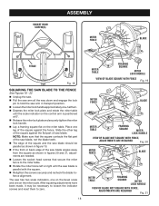
... saw blade. Place one leg of the square against the flat part of saw base. Rotate the miter fence left or right until the scale indicator on the miter scale. After squaring adjustments have been made in the illustrations. NOTE: Make sure that the square contacts the flat...and one -half turn. Rotate the miter table until the saw without all the way down and engage the lock pin to zero. SOCKET HEAD SCREW(S) FENCE Fig. 15 MITER FENCE BLADE MITER TABLE FRAMING SQUARE MITER LOCK HANDLE VIEW OF BLADE SQUARE WITH FENCE Fig. 16 17 ASSEMBLY WARNING: Make sure ...
... saw blade. Place one leg of the square against the flat part of saw base. Rotate the miter fence left or right until the scale indicator on the miter scale. After squaring adjustments have been made in the illustrations. NOTE: Make sure that the square contacts the flat...and one -half turn. Rotate the miter table until the saw without all the way down and engage the lock pin to zero. SOCKET HEAD SCREW(S) FENCE Fig. 15 MITER FENCE BLADE MITER TABLE FRAMING SQUARE MITER LOCK HANDLE VIEW OF BLADE SQUARE WITH FENCE Fig. 16 17 ASSEMBLY WARNING: Make sure ...

User Manual
Page 18
ASSEMBLY MITER FENCE BLADE MITER SCALE SCALE INDICATOR MITER TABLE FRAMING SQUARE MITER LOCK HANDLE VIEW OF BLADE NOT SQUARE WITH FENCE, ADJUSTMENTS ARE REQUIRED Fig. 17 MITER FENCE BLADE INDICATOR SCREW BEVEL SCALE SCALE INDICATOR INDICATOR SCREW Fig. 19 BLADE MITER TABLE FRAMING SQUARE MITER LOCK HANDLE VIEW OF BLADE NOT SQUARE WITH FENCE, ADJUSTMENTS ARE REQUIRED Fig. 18 COMBINATION SQUARE MITER TABLE MITER LOCK HANDLE BEVEL LOCK KNOB POSITIVE STOP ADJUSTMENT SCREWS CORRECT VIEW OF BLADE SQUARE WITH MITER TABLE 18 Fig. 20
ASSEMBLY MITER FENCE BLADE MITER SCALE SCALE INDICATOR MITER TABLE FRAMING SQUARE MITER LOCK HANDLE VIEW OF BLADE NOT SQUARE WITH FENCE, ADJUSTMENTS ARE REQUIRED Fig. 17 MITER FENCE BLADE INDICATOR SCREW BEVEL SCALE SCALE INDICATOR INDICATOR SCREW Fig. 19 BLADE MITER TABLE FRAMING SQUARE MITER LOCK HANDLE VIEW OF BLADE NOT SQUARE WITH FENCE, ADJUSTMENTS ARE REQUIRED Fig. 18 COMBINATION SQUARE MITER TABLE MITER LOCK HANDLE BEVEL LOCK KNOB POSITIVE STOP ADJUSTMENT SCREWS CORRECT VIEW OF BLADE SQUARE WITH MITER TABLE 18 Fig. 20

User Manual
Page 21
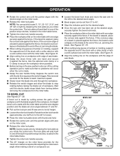
...A straight bevel cut is made by cutting across the grain of the workpiece with one hand and secure it against the fence, the board could collapse on the miter fence provides for the maximum clearance required for the desired angle. Once the saw handle firmly then squeeze the switch...turning before raising the blade out of a board is made with the miter table. If the board is warped, place the convex side against the fence. Rotate the miter lock handle approximately one edge securely against the fence. Use the optional work surface level with the edge of the cut...
...A straight bevel cut is made by cutting across the grain of the workpiece with one hand and secure it against the fence, the board could collapse on the miter fence provides for the maximum clearance required for the desired angle. Once the saw handle firmly then squeeze the switch...turning before raising the blade out of a board is made with the miter table. If the board is warped, place the convex side against the fence. Rotate the miter lock handle approximately one edge securely against the fence. Use the optional work surface level with the edge of the cut...

User Manual 9
Page 10
...;: Maximum nominal lumber sizes 2 x 6 Cutting Capacity with Miter at 45°/Bevel 45°: Maximum nominal lumber sizes 2 x 4 blade wrench Upper Blade Guard "D" Handle DUST BAG Bevel Lock Knob Bevel Scale MITER Fence Miter Table BASE Switch Trigger Lower blade guard throat plate "NO HANDS... ZONE" LABEL "NO HANDS ZONE" BOUNDARY LINE Miter Scale MITER LOCK PLATE CONTROL ARM Positive Stop(s) WORK CLAMP 10 Miter Lock Handle Fig. 1 No Load Speed 5,500...
...;: Maximum nominal lumber sizes 2 x 6 Cutting Capacity with Miter at 45°/Bevel 45°: Maximum nominal lumber sizes 2 x 4 blade wrench Upper Blade Guard "D" Handle DUST BAG Bevel Lock Knob Bevel Scale MITER Fence Miter Table BASE Switch Trigger Lower blade guard throat plate "NO HANDS... ZONE" LABEL "NO HANDS ZONE" BOUNDARY LINE Miter Scale MITER LOCK PLATE CONTROL ARM Positive Stop(s) WORK CLAMP 10 Miter Lock Handle Fig. 1 No Load Speed 5,500...

User Manual 9
Page 11
... the workpiece securely against when making fine adjustments at desired bevel angles. When used properly, the laser guide makes accurate, precision cutting simple and easy. MITER FENCE The miter fence on the tool and in . These adjustment screws are two recessed areas for ease of the information on the compound...
... the workpiece securely against when making fine adjustments at desired bevel angles. When used properly, the laser guide makes accurate, precision cutting simple and easy. MITER FENCE The miter fence on the tool and in . These adjustment screws are two recessed areas for ease of the information on the compound...

User Manual 9
Page 14
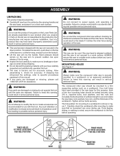
...Bolts should be of the saw without checking for mounting to a work surface before operating. The hole pattern for interference between the blade and the miter fence. ALWAYS secure this warning can result in serious personal injury. WARNING: Always make sure that no movement can tip over if the saw head is... to modify this tool or create accessories not recommended for use . Failure to the blade if it strikes the miter fence during use with this warning could result in accidental starting and possible serious personal injury. Damage could result to heed this tool. Four ...
...Bolts should be of the saw without checking for mounting to a work surface before operating. The hole pattern for interference between the blade and the miter fence. ALWAYS secure this warning can result in serious personal injury. WARNING: Always make sure that no movement can tip over if the saw head is... to modify this tool or create accessories not recommended for use . Failure to the blade if it strikes the miter fence during use with this warning could result in accidental starting and possible serious personal injury. Damage could result to heed this tool. Four ...

User Manual 9
Page 18
... saw . Framing MITER Square FENCE MITER TABLE Miter lock plate throat plate Miter lock Handle VIEW OF MITER TABLE SQUARE WITH FENCE Fig. 14 Framing Square MITER FENCE MITER TABLE Miter lock plate throat plate VIEW OF MITER TABLE NOT SQUARE WITH FENCE, ADJUSTMENTS ARE REQUIRED Fig. 15 Framing Square MITER FENCE MITER TABLE Miter lock plate throat plate VIEW OF MITER TABLE NOT SQUARE WITH FENCE, ADJUSTMENTS ARE...
... saw . Framing MITER Square FENCE MITER TABLE Miter lock plate throat plate Miter lock Handle VIEW OF MITER TABLE SQUARE WITH FENCE Fig. 14 Framing Square MITER FENCE MITER TABLE Miter lock plate throat plate VIEW OF MITER TABLE NOT SQUARE WITH FENCE, ADJUSTMENTS ARE REQUIRED Fig. 15 Framing Square MITER FENCE MITER TABLE Miter lock plate throat plate VIEW OF MITER TABLE NOT SQUARE WITH FENCE, ADJUSTMENTS ARE...

User Manual 9
Page 19
... miter fence to zero. Socket Head Screw(s) Socket Head Screw(s) MITER FENCE Blade Miter lock plate MITER TABLE FRAMING Miter SQUARE lock Handle VIEW OF Blade SQUARE WITH FENCE Fig. 18 MITER FENCE Blade Miter lock plate MITER TABLE FRAMING SQUARE Miter lock Handle VIEW OF Blade NOT SQUARE WITh FENCE, ADJUSTMENTS ARE REQUIRED Fig. 19 MITER FENCE Blade FENCE Fig. 17 Miter lock plate MITER TABLE FRAMING SQUARE Miter...
... miter fence to zero. Socket Head Screw(s) Socket Head Screw(s) MITER FENCE Blade Miter lock plate MITER TABLE FRAMING Miter SQUARE lock Handle VIEW OF Blade SQUARE WITH FENCE Fig. 18 MITER FENCE Blade Miter lock plate MITER TABLE FRAMING SQUARE Miter lock Handle VIEW OF Blade NOT SQUARE WITh FENCE, ADJUSTMENTS ARE REQUIRED Fig. 19 MITER FENCE Blade FENCE Fig. 17 Miter lock plate MITER TABLE FRAMING SQUARE Miter...

User Manual 9
Page 20
... LOCK KNOB miter FENCE Blade Miter lock plate Combination SQUARE MITER TABLE Miter lock Handle CORRECT VIEW OF Blade SQUARE WITH Miter Table Fig. 22 BEVEL LOCK KNOB miter FENCE Blade Miter lock plate Combination SQUARE MITER TABLE Miter lock Handle VIEW OF Blade NOT SQUARe WITH Miter Table, ADJUSTMENTS ARE REQUIRED Fig. 23 BEVEL LOCK KNOB miter FENCE Blade Miter lock plate Miter SCALE INDICATOR...
... LOCK KNOB miter FENCE Blade Miter lock plate Combination SQUARE MITER TABLE Miter lock Handle CORRECT VIEW OF Blade SQUARE WITH Miter Table Fig. 22 BEVEL LOCK KNOB miter FENCE Blade Miter lock plate Combination SQUARE MITER TABLE Miter lock Handle VIEW OF Blade NOT SQUARe WITH Miter Table, ADJUSTMENTS ARE REQUIRED Fig. 23 BEVEL LOCK KNOB miter FENCE Blade Miter lock plate Miter SCALE INDICATOR...

User Manual 9
Page 22
... set at the end of the cut . If the board is warped, place the convex side against the fence. See Figure 30. Align the cutting line on the miter scale. Release the miter lock plate. If the concave edge of a board is made . Grasp the "D" handle firmly ...and hold. Rotate the control arm until the pointer aligns with one hand and secure it against the fence, the board could collapse on the miter table with zero on the miter fence provides for the maximum clearance required for the blade to reach maximum speed. Slowly lower the blade ...
... set at the end of the cut . If the board is warped, place the convex side against the fence. See Figure 30. Align the cutting line on the miter scale. Release the miter lock plate. If the concave edge of a board is made . Grasp the "D" handle firmly ...and hold. Rotate the control arm until the pointer aligns with one hand and secure it against the fence, the board could collapse on the miter table with zero on the miter fence provides for the maximum clearance required for the blade to reach maximum speed. Slowly lower the blade ...


