English Manual
Page 12
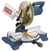
... the blade. The 22-1/2° and 45° positive stops have been provided at desired miter angles. It retracts over the upper blade guard as the saw at 0°, 15°, 22-1/2°, 30°, and 45°. Depress and hold the lock button while installing, changing, or ...removing blade. To prevent unauthorized use of the compound miter saw, disconnect it from rotating. diameter may be used. The miter lock handle securely locks the saw is lowered into the workpiece. The spindle lock button locks the spindle stopping the blade ...
... the blade. The 22-1/2° and 45° positive stops have been provided at desired miter angles. It retracts over the upper blade guard as the saw at 0°, 15°, 22-1/2°, 30°, and 45°. Depress and hold the lock button while installing, changing, or ...removing blade. To prevent unauthorized use of the compound miter saw, disconnect it from rotating. diameter may be used. The miter lock handle securely locks the saw is lowered into the workpiece. The spindle lock button locks the spindle stopping the blade ...
English Manual
Page 15
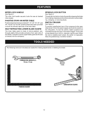
... base. Rotate the knob on the work clamp to secure the workpiece prior to the fence or the saw table. A dust bag is very helpful when cutting compound miters. Always make sure there is no interference with the stop block. To install the miter lock handle, place the threaded stud on... in the control arm. To remove the dust bag for use a C-clamp instead of serious personal injury. WARNING: When using any clamp with the blade guard prior to beginning any cutting operation to reduce the risk of the work clamp to tighten. It fits over the exhaust port on the same...
... base. Rotate the knob on the work clamp to secure the workpiece prior to the fence or the saw table. A dust bag is very helpful when cutting compound miters. Always make sure there is no interference with the stop block. To install the miter lock handle, place the threaded stud on... in the control arm. To remove the dust bag for use a C-clamp instead of serious personal injury. WARNING: When using any clamp with the blade guard prior to beginning any cutting operation to reduce the risk of the work clamp to tighten. It fits over the exhaust port on the same...
English Manual
Page 18
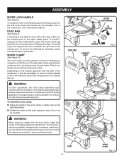
Never operate the saw arm to its full raised position. Loosen the miter lock handle approximately one leg of the framing ... securely tighten the miter lock handle. Lay a framing square flat on the saw arm and pull out the lock pin to release the saw arm. Raise saw without all guards securely in place and in the illustrations. Adjust the fence left or right until the ... in the miter table. SQUARING THE MITER TABLE TO THE FENCE See Figures 14 - 17. Unplug the saw . Place the other leg of the compound miter saw . Push down on the miter table.
Never operate the saw arm to its full raised position. Loosen the miter lock handle approximately one leg of the framing ... securely tighten the miter lock handle. Lay a framing square flat on the saw arm and pull out the lock pin to release the saw arm. Raise saw without all guards securely in place and in the illustrations. Adjust the fence left or right until the ... in the miter table. SQUARING THE MITER TABLE TO THE FENCE See Figures 14 - 17. Unplug the saw . Place the other leg of the compound miter saw . Push down on the miter table.
Repair Sheet
Page 3
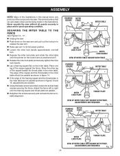
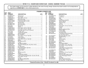
COMPOUND MITER SAW - KEY PART NO. Key Nos. 59-61 1 No Hands Warning Label 1 Retaining Ring 1 Roller 1 Torsion Spring 1 Blade Bolt 1 Laser Guide 1 Blade 1 Inner Blade Washer 1 * Screw (M4 x 9 mm, Pan Hd 1 * Screw (M5 x 10 mm, Pan Hd 4 Data Label 1 Upper Blade Guard Assembly (Inc...Pan Hd 1 Stopper 1 E-Clip 1 Retaining Spring Holder 1 * Washer (M6 1 * Lock Nut (M6 1 Shoulder Screw 1 Lower Blade Guard Assembly (Inc. RYOBI 10 in all correspondence regarding your MITER SAW or when ordering repair parts. Key Nos. 24-26 1 O-Ring 1 * Hex Nut (M10 1 * Fixed Screw (M10 x 20 mm...
COMPOUND MITER SAW - KEY PART NO. Key Nos. 59-61 1 No Hands Warning Label 1 Retaining Ring 1 Roller 1 Torsion Spring 1 Blade Bolt 1 Laser Guide 1 Blade 1 Inner Blade Washer 1 * Screw (M4 x 9 mm, Pan Hd 1 * Screw (M5 x 10 mm, Pan Hd 4 Data Label 1 Upper Blade Guard Assembly (Inc...Pan Hd 1 Stopper 1 E-Clip 1 Retaining Spring Holder 1 * Washer (M6 1 * Lock Nut (M6 1 Shoulder Screw 1 Lower Blade Guard Assembly (Inc. RYOBI 10 in all correspondence regarding your MITER SAW or when ordering repair parts. Key Nos. 24-26 1 O-Ring 1 * Hex Nut (M10 1 * Fixed Screw (M10 x 20 mm...
Repair Sheet
Page 5
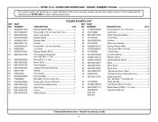
...mm 1 Operator's Manual * Standard Hardware Item - MODEL NUMBER TS1342L The model number will be found on a plate attached to the motor housing. KEY PART NO. COMPOUND MITER SAW - RYOBI 10 in all correspondence regarding your MITER SAW or when ordering repair parts. Key Nos. 11-16 1 ...089100212705 * Screw (M4 x 8 mm, Flat Hd 4 42 518106300 Throat Plate (Table Insert 1 43 A07003100256 Miter Table 1 44 089100207113 Fence 1 987000329 Safety Guard 1 8-05-08 (Rev:01) DESCRIPTION QTY. * Screw (M4 x 9 mm, Pan Hd 2 Grommet 1 Work Clamp Assembly 1 Lock Plate 1 Pointer ...
...mm 1 Operator's Manual * Standard Hardware Item - MODEL NUMBER TS1342L The model number will be found on a plate attached to the motor housing. KEY PART NO. COMPOUND MITER SAW - RYOBI 10 in all correspondence regarding your MITER SAW or when ordering repair parts. Key Nos. 11-16 1 ...089100212705 * Screw (M4 x 8 mm, Flat Hd 4 42 518106300 Throat Plate (Table Insert 1 43 A07003100256 Miter Table 1 44 089100207113 Fence 1 987000329 Safety Guard 1 8-05-08 (Rev:01) DESCRIPTION QTY. * Screw (M4 x 9 mm, Pan Hd 2 Grommet 1 Work Clamp Assembly 1 Lock Plate 1 Pointer ...


