Operation Manual
Page 3
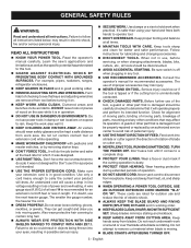
...to do so could occur if the tool is tipped or if the cutting tool is unintentionally contacted. CHECK DAMAGED PARTS. If in loss of parts, mounting and any tool. USE RECOMMENDED ACCESSORIES. Also wear protective hair covering to disconnect from receptacle. Failure to carry...; SECURE WORK. It's safer than using your eyes, resulting in operation. DO NOT USE IN DANGEROUS ENVIRONMENTS. A guard or other part that may affect its intended function. READ ALL INSTRUCTIONS KNOW YOUR POWER TOOL. Keep the work or around or over the blade while ...
...to do so could occur if the tool is tipped or if the cutting tool is unintentionally contacted. CHECK DAMAGED PARTS. If in loss of parts, mounting and any tool. USE RECOMMENDED ACCESSORIES. Also wear protective hair covering to disconnect from receptacle. Failure to carry...; SECURE WORK. It's safer than using your eyes, resulting in operation. DO NOT USE IN DANGEROUS ENVIRONMENTS. A guard or other part that may affect its intended function. READ ALL INSTRUCTIONS KNOW YOUR POWER TOOL. Keep the work or around or over the blade while ...
Operation Manual
Page 4
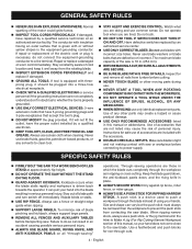
...the blade resulting in ripping or cross cutting. Through-sawing operations are defective or incorrect. English Do not use only identical replacement parts. Use of any solvents to power supply. Kickback occurs when the blade stalls rapidly and workpiece is the equipment-grounding conductor....LEG STAND at an authorized service facility. When ripping narrow stock, always use brake fluids, gasoline, petroleum-based products, or any other moving parts during use. NEVER START A TOOL WHEN ANY ROTATING COMPONENT IS IN CONTACT WITH THE WORKPIECE. DO NOT OPERATE A...
...the blade resulting in ripping or cross cutting. Through-sawing operations are defective or incorrect. English Do not use only identical replacement parts. Use of any solvents to power supply. Kickback occurs when the blade stalls rapidly and workpiece is the equipment-grounding conductor....LEG STAND at an authorized service facility. When ripping narrow stock, always use brake fluids, gasoline, petroleum-based products, or any other moving parts during use. NEVER START A TOOL WHEN ANY ROTATING COMPONENT IS IN CONTACT WITH THE WORKPIECE. DO NOT OPERATE A...
Operation Manual
Page 5
... saw blade. NEVER reach behind, over the saw . ALWAYS TURN OFF SAW before it is twisted or warped or does not have any part of your body in line with safe operation BEFORE performing any work . NEVER stand or have a straight edge to guide along the fence. ...
... saw blade. NEVER reach behind, over the saw . ALWAYS TURN OFF SAW before it is twisted or warped or does not have any part of your body in line with safe operation BEFORE performing any work . NEVER stand or have a straight edge to guide along the fence. ...
Operation Manual
Page 8
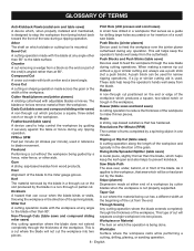
... over , under, behind, or in the direction of the blade to the miter gauge groove. Chamfer A cut removing a wedge from a block so the end (or part of the cut will separate a single workpiece into two pieces. Push Blocks (jointer planers) Device used . Resin A sticky, sap-based substance that serves as a guide...
... over , under, behind, or in the direction of the blade to the miter gauge groove. Chamfer A cut removing a wedge from a block so the end (or part of the cut will separate a single workpiece into two pieces. Push Blocks (jointer planers) Device used . Resin A sticky, sap-based substance that serves as a guide...
Operation Manual
Page 13
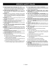
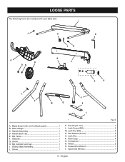
Miter Gauge 1 C. Rip Fence 1 F. Lock Screw (M5 4 M. Stand Leg 4 Q. Crosspiece 1 R. Handle Assembly 1 D. Screw 1 H. Rip indicator end cap 1 I J H K FG A R ON B E C D L P P M Q S T A. Screw 1 Fig. 5 K. Hex Key (5 mm 1 L. Flat Washer (8 mm 4 O. Wheel 2 S. Sliding Table Assembly 1 J. Open End Wrench 1 13 - Lock Nut (M5 4 N. English Lock Nut 2 P. Indicator 1 G. Handle End Cap 1 E. LOOSE PARTS The following items are included with anti-kickback pawls 1 B. Closed End Wrench 1 T. Blade Guard with your table saw: I .
Miter Gauge 1 C. Rip Fence 1 F. Lock Screw (M5 4 M. Stand Leg 4 Q. Crosspiece 1 R. Handle Assembly 1 D. Screw 1 H. Rip indicator end cap 1 I J H K FG A R ON B E C D L P P M Q S T A. Screw 1 Fig. 5 K. Hex Key (5 mm 1 L. Flat Washer (8 mm 4 O. Wheel 2 S. Sliding Table Assembly 1 J. Open End Wrench 1 13 - Lock Nut (M5 4 N. English Lock Nut 2 P. Indicator 1 G. Handle End Cap 1 E. LOOSE PARTS The following items are included with anti-kickback pawls 1 B. Closed End Wrench 1 T. Blade Guard with your table saw: I .

Operation Manual
Page 14
...use with other equipment or for assistance. WARNING: Do not connect to come closer than 3 in this manual. If any parts are replaced. Ignoring these precautions can result in serious personal injury. Inspect the tool carefully to make sure no movement can occur... in . Four bolt holes have been improperly assembled could result in place. 14 - Failure to possible serious personal injury. Tighten all loose parts, and satisfactorily operated the tool. The saw 's frame for accurate cutting. To mount the saw without help when needed. English NOTE...
...use with other equipment or for assistance. WARNING: Do not connect to come closer than 3 in this manual. If any parts are replaced. Ignoring these precautions can result in serious personal injury. Inspect the tool carefully to make sure no movement can occur... in . Four bolt holes have been improperly assembled could result in place. 14 - Failure to possible serious personal injury. Tighten all loose parts, and satisfactorily operated the tool. The saw 's frame for accurate cutting. To mount the saw without help when needed. English NOTE...

Operation Manual
Page 15
... legs with two holes drilled into it. NOTE: Do NOT overtighten as shown, aligning the holes in the crosspiece with the holes in the lower part of the stand. Slide each of the saw. (See Figure 6.) INSTALLING STAND LEGS Assemble each bolt. English LEG HOLES BOLT PIVOT PLATE OUTER...
... legs with two holes drilled into it. NOTE: Do NOT overtighten as shown, aligning the holes in the crosspiece with the holes in the lower part of the stand. Slide each of the saw. (See Figure 6.) INSTALLING STAND LEGS Assemble each bolt. English LEG HOLES BOLT PIVOT PLATE OUTER...

Operation Manual
Page 21
... for through cuts. ASSEMBLY INSTALLING THE BLADE GUARD See Figures 17 - 18. BLADE GUARD WARNING: Replace the blade guard if the anti-kickback pawls are part of serious personal injury. Anti-kickback pawls are dull or damaged. When not needed, they may not stop a kickback increasing the risk of the blade...
... for through cuts. ASSEMBLY INSTALLING THE BLADE GUARD See Figures 17 - 18. BLADE GUARD WARNING: Replace the blade guard if the anti-kickback pawls are part of serious personal injury. Anti-kickback pawls are dull or damaged. When not needed, they may not stop a kickback increasing the risk of the blade...

Operation Manual
Page 42
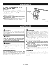
... blade guard assembly. After extensive use, they may need to adjust if needed. If needed . NOTE: Make sure that the square contacts the flat part of the saw table surface so the workpiece doesn't catch on the right. If unable to make this adjustment, take the product to 45°... square beside the blade on uneven edges. The edge of the saw blade should be parallel. NOTE: Make sure that the square contacts the flat part of the square and the saw blade, not the blade teeth. Lock the bevel locking lever. Tighten the adjustment screw. The edge of...
... blade guard assembly. After extensive use, they may need to adjust if needed. If needed . NOTE: Make sure that the square contacts the flat part of the saw table surface so the workpiece doesn't catch on the right. If unable to make this adjustment, take the product to 45°... square beside the blade on uneven edges. The edge of the saw blade should be parallel. NOTE: Make sure that the square contacts the flat part of the square and the saw blade, not the blade teeth. Lock the bevel locking lever. Tighten the adjustment screw. The edge of...
Operation Manual
Page 44
... the tool is unplugged from various types of commercial solvents and may result in the OFF ( O ) position. WARNING: Before performing any other parts may create a hazard or cause product damage. Chemicals can damage, weaken, or destroy plastic which may be difficult to push down and lock. ... OF THE RIP FENCE LOCKING LEVER See Figure 56. If operation is required. 44 - GENERAL MAINTENANCE Avoid using solvents when cleaning plastic parts. WARNING: Do not at any aerosol or petroleum solvents. Failure to provide smooth functioning. Protect the blade by their use only...
... the tool is unplugged from various types of commercial solvents and may result in the OFF ( O ) position. WARNING: Before performing any other parts may create a hazard or cause product damage. Chemicals can damage, weaken, or destroy plastic which may be difficult to push down and lock. ... OF THE RIP FENCE LOCKING LEVER See Figure 56. If operation is required. 44 - GENERAL MAINTENANCE Avoid using solvents when cleaning plastic parts. WARNING: Do not at any aerosol or petroleum solvents. Failure to provide smooth functioning. Protect the blade by their use only...

Parts Diagram
Page 3
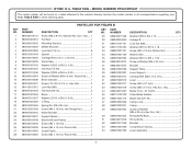
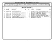
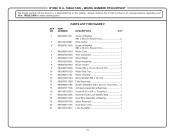
... Hd 2 18 089110101024 Screw w/Washer (M6 x 12 mm, Hex. Hd 4 27 089110101014 Screw (#10 x 1/2 in . TABLE SAW or when ordering parts. Soc. MODEL NUMBER RTS22/RTS22T The model number will be found on a label attached to the cabinet. Key Nos. 39 and 44-46 1 12 089037007006 Push Stick 1 13... Spring 2 8 089240015094 Latch 1 9 080015001505 Combination Blade Wrench 1 10 080015001506 Open End Wrench 1 11 089240016120 Rear Outfeed Support Assembly (Inc. NUMBER DESCRIPTION QTY KEY PART NO. RYOBI 10 in. PARTS LIST FOR FIGURE A KEY...
... Hd 2 18 089110101024 Screw w/Washer (M6 x 12 mm, Hex. Hd 4 27 089110101014 Screw (#10 x 1/2 in . TABLE SAW or when ordering parts. Soc. MODEL NUMBER RTS22/RTS22T The model number will be found on a label attached to the cabinet. Key Nos. 39 and 44-46 1 12 089037007006 Push Stick 1 13... Spring 2 8 089240015094 Latch 1 9 080015001505 Combination Blade Wrench 1 10 080015001506 Open End Wrench 1 11 089240016120 Rear Outfeed Support Assembly (Inc. NUMBER DESCRIPTION QTY KEY PART NO. RYOBI 10 in. PARTS LIST FOR FIGURE A KEY...
Parts Diagram
Page 5
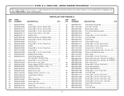
...1 19 089037007029 C-Ring 1 20 080015001458 Spring Pin (D8 x 90 mm 1 44 089240015207 Blade (10 in . RYOBI 10 in . MODEL NUMBER RTS22/RTS22T The model number will be found on a label attached to the cabinet. Hd.)......1 2 089037007012 Pull Rod 1 ...Hd 2 6 080015001449 Spacer 2 7 089240015034 Carriage Bolt (1/4 in . TABLE SAW or when ordering parts. NUMBER DESCRIPTION QTY 1 089240015112 Screw (M6 x 8 mm, Special Hex. NUMBER DESCRIPTION QTY KEY PART NO. x 45 mm 1 8 089240015209 Work Plate 1 9 089037007102 Washer (OD20 x ID6.5 x...
...1 19 089037007029 C-Ring 1 20 080015001458 Spring Pin (D8 x 90 mm 1 44 089240015207 Blade (10 in . RYOBI 10 in . MODEL NUMBER RTS22/RTS22T The model number will be found on a label attached to the cabinet. Hd.)......1 2 089037007012 Pull Rod 1 ...Hd 2 6 080015001449 Spacer 2 7 089240015034 Carriage Bolt (1/4 in . TABLE SAW or when ordering parts. NUMBER DESCRIPTION QTY 1 089240015112 Screw (M6 x 8 mm, Special Hex. NUMBER DESCRIPTION QTY KEY PART NO. x 45 mm 1 8 089240015209 Work Plate 1 9 089037007102 Washer (OD20 x ID6.5 x...
Parts Diagram
Page 6
...20 x 3/4 in . TABLE SAW - NUMBER DESCRIPTION QTY KEY PART NO. MODEL NUMBER RTS22/RTS22T The model number will be found on a label attached to the cabinet. PARTS LIST FOR FIGURE B KEY PART NO. Always mention the model number in all correspondence regarding your 10... in ., Hex Flange Hd.)..........1 67 089240015089 Lock Nut (M4 1 6 RYOBI 10 in. TABLE SAW or when ordering parts...
...20 x 3/4 in . TABLE SAW - NUMBER DESCRIPTION QTY KEY PART NO. MODEL NUMBER RTS22/RTS22T The model number will be found on a label attached to the cabinet. PARTS LIST FOR FIGURE B KEY PART NO. Always mention the model number in all correspondence regarding your 10... in ., Hex Flange Hd.)..........1 67 089240015089 Lock Nut (M4 1 6 RYOBI 10 in. TABLE SAW or when ordering parts...
Parts Diagram
Page 8
RYOBI 10 in ., Hex Hd 2 Washer (D4 2 External Tooth Lock Washer (M4 2 Screw (M5 x 30 mm... mm, Round Hd 4 Screw (8-32 x 3/8 in . Key No. 50, RTS22)..... 1 Dust Chute Assy. (Inc. Hd 1 Screw (M6 x 20 mm, Truss Soc. TABLE SAW - NUMBER DESCRIPTION QTY KEY PART NO. x 1.5t 1 31 32 33 34 35 36 37 38 39 40 ... Warning Label 1 Wire Clamp 1 Screw (M4 x 10 mm, Truss Hd 1 Dust Chute Assy. (Inc. TABLE SAW or when ordering parts. PARTS LIST FOR FIGURE C KEY PART NO. x 1t 1 Compression Spring 1 Cap 1 Hand Wheel Cap 1 Hand Grip Cap 1 Screw (1/4-20 x 55 mm 1 Hand Grip...
RYOBI 10 in ., Hex Hd 2 Washer (D4 2 External Tooth Lock Washer (M4 2 Screw (M5 x 30 mm... mm, Round Hd 4 Screw (8-32 x 3/8 in . Key No. 50, RTS22)..... 1 Dust Chute Assy. (Inc. Hd 1 Screw (M6 x 20 mm, Truss Soc. TABLE SAW - NUMBER DESCRIPTION QTY KEY PART NO. x 1.5t 1 31 32 33 34 35 36 37 38 39 40 ... Warning Label 1 Wire Clamp 1 Screw (M4 x 10 mm, Truss Hd 1 Dust Chute Assy. (Inc. TABLE SAW or when ordering parts. PARTS LIST FOR FIGURE C KEY PART NO. x 1t 1 Compression Spring 1 Cap 1 Hand Wheel Cap 1 Hand Grip Cap 1 Screw (1/4-20 x 55 mm 1 Hand Grip...
Parts Diagram
Page 10
... Screw (M4 x 12 mm, Flat Hd 1 8 089240015172 Push Stick Holder 1 9 089240015162 Rip Fence 1 10 089110101107 Screw (M6 x 15 mm, Truss Soc. MODEL NUMBER RTS22/RTS22T The model number will be found on a label attached to the cabinet. TABLE SAW or when ordering parts. PARTS LIST FOR FIGURE D KEY PART NO. TABLE SAW - RYOBI 10 in .
... Screw (M4 x 12 mm, Flat Hd 1 8 089240015172 Push Stick Holder 1 9 089240015162 Rip Fence 1 10 089110101107 Screw (M6 x 15 mm, Truss Soc. MODEL NUMBER RTS22/RTS22T The model number will be found on a label attached to the cabinet. TABLE SAW or when ordering parts. PARTS LIST FOR FIGURE D KEY PART NO. TABLE SAW - RYOBI 10 in .
Parts Diagram
Page 11
... 1 2 080015001563 Pointer 1 3 080015001662 Screw (3/16-24 x 1/4 in . TABLE SAW - TABLE SAW or when ordering parts. Hd 1 4 089037007078 Screw (M4 X 14.8 MM 1 5 089040002706 Miter Gauge 1 6 080015001475 Nylon Washer (OD16 x ID6.5 x 2t 1 7 080015001560 Washer (OD16 x ID6.5 x 2t 1 8 089040002005 Miter Gauge Knob 1 9 089040002006 Miter Gauge Cap 1 1 4 3 2 11 RYOBI 10 in. FIGURE E 9 8 7 6 5 PARTS LIST FOR FIGURE E KEY...
... 1 2 080015001563 Pointer 1 3 080015001662 Screw (3/16-24 x 1/4 in . TABLE SAW - TABLE SAW or when ordering parts. Hd 1 4 089037007078 Screw (M4 X 14.8 MM 1 5 089040002706 Miter Gauge 1 6 080015001475 Nylon Washer (OD16 x ID6.5 x 2t 1 7 080015001560 Washer (OD16 x ID6.5 x 2t 1 8 089040002005 Miter Gauge Knob 1 9 089040002006 Miter Gauge Cap 1 1 4 3 2 11 RYOBI 10 in. FIGURE E 9 8 7 6 5 PARTS LIST FOR FIGURE E KEY...
Parts Diagram
Page 12
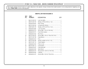
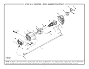
To avoid the possibility of the double insulated system. RYOBI 10 in. MODEL NUMBER RTS22/RTS22T 20 21 19 18 7 8 11 3 14 13 12 10 9 87 6 1 1 2 4 15 17 17 16 14 FIGURE F 5 NOTE: The assembly shown represents an important part of alteration or damage to the system, service should be performed by your nearest Ryobi Authorized Service Center for service. 12 Contact your nearest Ryobi Authorized Service Center. TABLE SAW -
To avoid the possibility of the double insulated system. RYOBI 10 in. MODEL NUMBER RTS22/RTS22T 20 21 19 18 7 8 11 3 14 13 12 10 9 87 6 1 1 2 4 15 17 17 16 14 FIGURE F 5 NOTE: The assembly shown represents an important part of alteration or damage to the system, service should be performed by your nearest Ryobi Authorized Service Center for service. 12 Contact your nearest Ryobi Authorized Service Center. TABLE SAW -
Parts Diagram
Page 13
... 14 089290001182 Screw w/Washer (M5 x 65 mm, Truss Hd.)...... 2 15 089037011708 Armature Assembly w/Bearings 1 16 089110101220 Screw (8-32 x 3/8 in . MODEL NUMBER RTS22/RTS22T The model number will be found on a label attached to the cabinet. TABLE SAW - Hd 2 2 089110101081 Wire Clamp 1 3 089037011050 Screw w/Washer (M5...Arbor Assembly 1 20 089240015139 Gear Box Cover 1 21 089110101012 Lock Nut (M5 1 13 TABLE SAW or when ordering parts. RYOBI 10 in. NUMBER DESCRIPTION QTY 1 089240015141 Screw w/Washer (M5 x 60 mm, Round.
... 14 089290001182 Screw w/Washer (M5 x 65 mm, Truss Hd.)...... 2 15 089037011708 Armature Assembly w/Bearings 1 16 089110101220 Screw (8-32 x 3/8 in . MODEL NUMBER RTS22/RTS22T The model number will be found on a label attached to the cabinet. TABLE SAW - Hd 2 2 089110101081 Wire Clamp 1 3 089037011050 Screw w/Washer (M5...Arbor Assembly 1 20 089240015139 Gear Box Cover 1 21 089110101012 Lock Nut (M5 1 13 TABLE SAW or when ordering parts. RYOBI 10 in. NUMBER DESCRIPTION QTY 1 089240015141 Screw w/Washer (M5 x 60 mm, Round.
Parts Diagram
Page 14
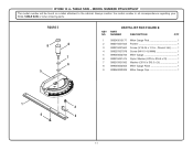
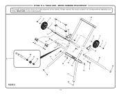
TABLE SAW or when ordering parts. 1 2 3 10 4 2 5 12 11 1 2 3 6 8 7 9 2 1 1 13 20 15 21 17 9 22 19 16 14 15 18 8 16 18 17 FIGURE G 18 14 RYOBI 10 in . MODEL NUMBER RTS22/RTS22T The model number will be found on a label attached to the cabinet. Always mention the model number in all correspondence regarding your 10 in . TABLE SAW -
TABLE SAW or when ordering parts. 1 2 3 10 4 2 5 12 11 1 2 3 6 8 7 9 2 1 1 13 20 15 21 17 9 22 19 16 14 15 18 8 16 18 17 FIGURE G 18 14 RYOBI 10 in . MODEL NUMBER RTS22/RTS22T The model number will be found on a label attached to the cabinet. Always mention the model number in all correspondence regarding your 10 in . TABLE SAW -

Parts Diagram
Page 15
... 1 Not Shown: 089240016702 Complete Stand Assembly (Inc. Always mention the model number in all correspondence regarding your 10 in . Key Nos. 1-22) 15 PARTS LIST FOR FIGURE G KEY PART NO. TABLE SAW or when ordering parts. RYOBI 10 in. MODEL NUMBER RTS22/RTS22T The model number will be found on a label attached to the cabinet.
... 1 Not Shown: 089240016702 Complete Stand Assembly (Inc. Always mention the model number in all correspondence regarding your 10 in . Key Nos. 1-22) 15 PARTS LIST FOR FIGURE G KEY PART NO. TABLE SAW or when ordering parts. RYOBI 10 in. MODEL NUMBER RTS22/RTS22T The model number will be found on a label attached to the cabinet.


