Operation Manual
Page 3
.... A wire gauge size (A.W.G.) of operation. DO NOT ABUSE CORD. TURN THE POWER OFF. Don't leave tool until it for outdoor use of electric shock. ALWAYS KEEP THE BLADE GUARD AND RIVING KNIFE (SPLITTER) IN PLACE and in length. Failure to operate tool. DON'T OVERREACH. Make sure your hand and frees both hands to follow all tools should wear safety glasses and be disconnected. AVOID ACCIDENTAL STARTING...
.... A wire gauge size (A.W.G.) of operation. DO NOT ABUSE CORD. TURN THE POWER OFF. Don't leave tool until it for outdoor use of electric shock. ALWAYS KEEP THE BLADE GUARD AND RIVING KNIFE (SPLITTER) IN PLACE and in length. Failure to operate tool. DON'T OVERREACH. Make sure your hand and frees both hands to follow all tools should wear safety glasses and be disconnected. AVOID ACCIDENTAL STARTING...
Operation Manual
Page 4
... blade. INSPECT EXTENSION CORDS PERIODICALLY and replace if damaged. GROUND ALL TOOLS. Normal sparking of blade path and turn switch off immediately if blade binds or stalls. USE RIP FENCE. Do not rush. DO NOT USE TOOL IF SWITCH DOES NOT TURN IT ON AND OFF. SPECIFIC SAFETY RULES FIRMLY BOLT THE SAW TO A WORK BENCH OR LEG STAND at an authorized service facility. GENERAL SAFETY...
... blade. INSPECT EXTENSION CORDS PERIODICALLY and replace if damaged. GROUND ALL TOOLS. Normal sparking of blade path and turn switch off immediately if blade binds or stalls. USE RIP FENCE. Do not rush. DO NOT USE TOOL IF SWITCH DOES NOT TURN IT ON AND OFF. SPECIFIC SAFETY RULES FIRMLY BOLT THE SAW TO A WORK BENCH OR LEG STAND at an authorized service facility. GENERAL SAFETY...
Operation Manual
Page 5
... the rip fence or miter gauge to instructions on floor or below waist height. NEVER CUT MORE THAN ONE PIECE OF MATERIAL AT A TIME. SAVE THESE INSTRUCTIONS. e) Pay particular attention to position and guide the work using the table saw. ALWAYS TURN OFF SAW before it is twisted or warped or does not have a straight edge to guide along the fence. IF THE POWER SUPPLY CORD...
... the rip fence or miter gauge to instructions on floor or below waist height. NEVER CUT MORE THAN ONE PIECE OF MATERIAL AT A TIME. SAVE THESE INSTRUCTIONS. e) Pay particular attention to position and guide the work using the table saw. ALWAYS TURN OFF SAW before it is twisted or warped or does not have a straight edge to guide along the fence. IF THE POWER SUPPLY CORD...

Operation Manual
Page 7
... 12 gauge - 20 amp circuit. Repair or replace a damaged or worn cord immediately. It should be grounded. When using an extension cord, inspect it will overheat. This tool is 120 V, AC only (normal household current), 60 Hz. ELECTRICAL EXTENSION CORDS Use only 3-wire extension cords that have the proper outlet installed by a precision built electric motor. Before using a power tool at a considerable distance from the power source, use . SPEED AND WIRING The no-load speed...
... 12 gauge - 20 amp circuit. Repair or replace a damaged or worn cord immediately. It should be grounded. When using an extension cord, inspect it will overheat. This tool is 120 V, AC only (normal household current), 60 Hz. ELECTRICAL EXTENSION CORDS Use only 3-wire extension cords that have the proper outlet installed by a precision built electric motor. Before using a power tool at a considerable distance from the power source, use . SPEED AND WIRING The no-load speed...
Operation Manual
Page 8
... partial cut removing a wedge from a block so the end (or part of the workpiece. Chamfer A cut . Dado Cut (table saws and compound sliding miter saws) A non-through cut the workpiece into two pieces. Push Blocks and Push Sticks (table saws) Devices used . A push block can occur when the blade binds or stalls, throwing the workpiece in the workpiece. Worktable Surface where the workpiece rests while performing a cutting, drilling, planing, or sanding operation...
... partial cut removing a wedge from a block so the end (or part of the workpiece. Chamfer A cut . Dado Cut (table saws and compound sliding miter saws) A non-through cut the workpiece into two pieces. Push Blocks and Push Sticks (table saws) Devices used . A push block can occur when the blade binds or stalls, throwing the workpiece in the workpiece. Worktable Surface where the workpiece rests while performing a cutting, drilling, planing, or sanding operation...
Operation Manual
Page 10
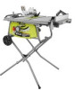
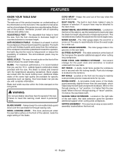
... with complete information. FEATURES KNOW YOUR TABLE SAW See Figure 2. Before use the 10 in the through -sawing cuts. The teeth on the rip fence. Bevel angles are available for bevel angles easy. This lever, placed just under the saw . The miter gauge aligns the wood for a miter cut . Convenient storage for rip cuts. A removable metal piece of the cabinet shows the exact blade angle. When in . SWITCH ASSEMBLY - This saw blade, which the workpiece is located...
... with complete information. FEATURES KNOW YOUR TABLE SAW See Figure 2. Before use the 10 in the through -sawing cuts. The teeth on the rip fence. Bevel angles are available for bevel angles easy. This lever, placed just under the saw . The miter gauge aligns the wood for a miter cut . Convenient storage for rip cuts. A removable metal piece of the cabinet shows the exact blade angle. When in . SWITCH ASSEMBLY - This saw blade, which the workpiece is located...
Operation Manual
Page 11
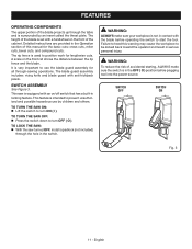
... be kicked back toward the operator and result in the switch. This feature is used to position work for lengthwise cuts. Failure to heed this manual for all through-sawing operations. The rip fence is intended to prevent unauthorized and possible hazardous use the blade guard assembly for the basic cuts: cross cuts, miter cuts, bevel cuts, and compound cuts. It is surrounded by children and others. Detailed instructions are provided in contact...
... be kicked back toward the operator and result in the switch. This feature is used to position work for lengthwise cuts. Failure to heed this manual for all through-sawing operations. The rip fence is intended to prevent unauthorized and possible hazardous use the blade guard assembly for the basic cuts: cross cuts, miter cuts, bevel cuts, and compound cuts. It is surrounded by children and others. Detailed instructions are provided in contact...

Operation Manual
Page 16
.... Insert the handle and screw into the hole on the height/ bevel adjusting handwheel. Using a flathead screwdriver, turn the screw clockwise and tighten in place. English AXLE WHEEL WASHER NUT WASHER Fig. 9 WASHER END HANDLE CAP BOLT WHEEL Fig. 10 16 - ASSEMBLY INSTALLING WHEELS ONTO THE STAND See Figure 9. INSTALLING THE HANDLE See Figure 10. Remove the hex nut from the bolt in the handle but do not remove the bolt. Slide a washer onto...
.... Insert the handle and screw into the hole on the height/ bevel adjusting handwheel. Using a flathead screwdriver, turn the screw clockwise and tighten in place. English AXLE WHEEL WASHER NUT WASHER Fig. 9 WASHER END HANDLE CAP BOLT WHEEL Fig. 10 16 - ASSEMBLY INSTALLING WHEELS ONTO THE STAND See Figure 9. INSTALLING THE HANDLE See Figure 10. Remove the hex nut from the bolt in the handle but do not remove the bolt. Slide a washer onto...

Operation Manual
Page 20
... for free blade rotation. BLADE WRENCH BLADE WRENCH BLADE NUT Fig. 16 20 - To loosen the blade: Remove the blade wrenches from the blade wrench storage area. Using blade wrenches, place the flat open end into the flats on the arbor shaft. Insert the closed end of the blade wrench over the blade nut. Failure to heed this warning could cause damage to its full height by turning the height/bevel adjusting handwheel...
... for free blade rotation. BLADE WRENCH BLADE WRENCH BLADE NUT Fig. 16 20 - To loosen the blade: Remove the blade wrenches from the blade wrench storage area. Using blade wrenches, place the flat open end into the flats on the arbor shaft. Insert the closed end of the blade wrench over the blade nut. Failure to heed this warning could cause damage to its full height by turning the height/bevel adjusting handwheel...

Operation Manual
Page 24
... purposes listed below: Straight line cutting operations such as cross cutting, ripping, mitering, beveling, and compound cutting Dado with dull blades. To avoid pinching the blade, support the work Forcing a cut Cutting warped or wet lumber Using the wrong blade for the type of cut Not following correct operating procedures Misusing the saw Failing to use the anti-kickback pawls Cutting with the blade guard removed for...
... purposes listed below: Straight line cutting operations such as cross cutting, ripping, mitering, beveling, and compound cutting Dado with dull blades. To avoid pinching the blade, support the work Forcing a cut Cutting warped or wet lumber Using the wrong blade for the type of cut Not following correct operating procedures Misusing the saw Failing to use the anti-kickback pawls Cutting with the blade guard removed for...

Operation Manual
Page 27
... against the miter gauge. Compound (or bevel) miter cuts are with an angled blade. RIP CUT MITER CUT WARNING: Always use blades rated less than the blade to finish the cut are across the grain of cut when ripping a long narrow piece of these cuts to the blade, and the blade is in the wood) will be controlled by the blade in place and working properly when making a rip cut . Always provide proper support for making...
... against the miter gauge. Compound (or bevel) miter cuts are with an angled blade. RIP CUT MITER CUT WARNING: Always use blades rated less than the blade to finish the cut are across the grain of cut when ripping a long narrow piece of these cuts to the blade, and the blade is in the wood) will be controlled by the blade in place and working properly when making a rip cut . Always provide proper support for making...

Operation Manual
Page 28
... TO DECREASE ANGLE HEIGHT/BEVEL ADJUSTING HANDWHEEL 28 - The blade depth should be set so that allows you to make angled cuts from 90° to the right. If it needs to be further loosened, pull spring-loaded bevel lock lever out and rotate it back to 45°. Retighten the screw. TO CHANGE BLADE ANGLE (BEVEL) See Figure 29. English Fig. 28 BEVEL LOCKING LEVER TO INCREASE ANGLE Fig. 29 BEVEL LOCKING LEVER SCREW BEVEL INDICATOR Fig...
... TO DECREASE ANGLE HEIGHT/BEVEL ADJUSTING HANDWHEEL 28 - The blade depth should be set so that allows you to make angled cuts from 90° to the right. If it needs to be further loosened, pull spring-loaded bevel lock lever out and rotate it back to 45°. Retighten the screw. TO CHANGE BLADE ANGLE (BEVEL) See Figure 29. English Fig. 28 BEVEL LOCKING LEVER TO INCREASE ANGLE Fig. 29 BEVEL LOCKING LEVER SCREW BEVEL INDICATOR Fig...
Operation Manual
Page 31
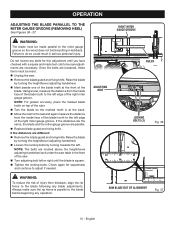
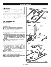
... same, the blade and the miter gauge groove are different: Remove the blade guard and riving knife. OPERATION ADJUSTING THE BLADE PARALLEL TO THE MITER GAUGE GROOVE (REMOVING HEEL) See Figures 36 - 37. Using a ruler, measure the distance from kickback, align the rip fence to do so could result in the front of the saw. Turn adjusting bolt left edge of the blade tooth to the miter gauge groove so...
... same, the blade and the miter gauge groove are different: Remove the blade guard and riving knife. OPERATION ADJUSTING THE BLADE PARALLEL TO THE MITER GAUGE GROOVE (REMOVING HEEL) See Figures 36 - 37. Using a ruler, measure the distance from kickback, align the rip fence to do so could result in the front of the saw. Turn adjusting bolt left edge of the blade tooth to the miter gauge groove so...
Operation Manual
Page 32
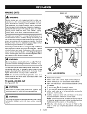
... to power source. Use the miter gauge when making any cuts not covered here unless you place the piece to a complete stop before moving the workpiece into the blade. English OPERATION MAKING CUTS WARNING: Before making cross, miter, bevel, and compound miter cuts. Operating the saw in this manual. Carefully check all mentioned in a location that are thoroughly familiar with the proper procedures and necessary accessories. Always tighten the lock knob securely...
... to power source. Use the miter gauge when making any cuts not covered here unless you place the piece to a complete stop before moving the workpiece into the blade. English OPERATION MAKING CUTS WARNING: Before making cross, miter, bevel, and compound miter cuts. Operating the saw in this manual. Carefully check all mentioned in a location that are thoroughly familiar with the proper procedures and necessary accessories. Always tighten the lock knob securely...

Operation Manual
Page 33
... injury. OPERATION MAKING A RIP CUT See Figure 40. Do not attempt a free hand taper cut is installed and working properly to avoid possible serious injury. Remove the rip fence. Set the blade to the correct depth for the blade to come to the blade should be placed on the miter gauge lock knob and the hand farthest from the blade should be made , turn the saw . Make sure the edge of the table. MITER GAUGE ANGLED MITER CUT BLADE STRAIGHT...
... injury. OPERATION MAKING A RIP CUT See Figure 40. Do not attempt a free hand taper cut is installed and working properly to avoid possible serious injury. Remove the rip fence. Set the blade to the correct depth for the blade to come to the blade should be placed on the miter gauge lock knob and the hand farthest from the blade should be made , turn the saw . Make sure the edge of the table. MITER GAUGE ANGLED MITER CUT BLADE STRAIGHT...

Operation Manual
Page 35
... bevel locking lever. Adjust the bevel angle to the desired setting. Lock the bevel locking lever. Set the blade to the correct depth for the workpiece. Position the rip fence the desired distance from the blade for the cut and securely lock the handle. Make sure the wood is installed and working properly to a complete stop before removing the workpiece. OPERATION MAKING A BEVEL RIP CUT See Figure 44. Make sure the edge of the table...
... bevel locking lever. Adjust the bevel angle to the desired setting. Lock the bevel locking lever. Set the blade to the correct depth for the workpiece. Position the rip fence the desired distance from the blade for the cut and securely lock the handle. Make sure the wood is installed and working properly to a complete stop before removing the workpiece. OPERATION MAKING A BEVEL RIP CUT See Figure 44. Make sure the edge of the table...

Operation Manual
Page 36
... full speed before removing the workpiece. Fig. 45 36 - English COMPOUND (BEVEL) MITER CUT PLACE LEFT HAND ON MITER GAUGE HERE WARNING: The miter gauge must be placed on the workpiece. When the cut is clear of the blade before turning on the right side of serious personal injury. Remove the rip fence. Unlock the bevel locking lever. Adjust the bevel angle to the desired setting. Lock the bevel locking lever. Set the blade...
... full speed before removing the workpiece. Fig. 45 36 - English COMPOUND (BEVEL) MITER CUT PLACE LEFT HAND ON MITER GAUGE HERE WARNING: The miter gauge must be placed on the workpiece. When the cut is clear of the blade before turning on the right side of serious personal injury. Remove the rip fence. Unlock the bevel locking lever. Adjust the bevel angle to the desired setting. Lock the bevel locking lever. Set the blade...
Operation Manual
Page 41
... the saw blade and remove the throat plate. Make sure the bevel locking lever is securely tightened. Remove the blade nut and blade washer. Unlock the release locking lever and remove the blade. To install a standard blade: Place the new blade on the arbor shaft. Insert the closed end of the blade wrench over the arbor shaft. NOTE: To replace the blade with an accessory blade, follow the instructions provided with a framing square and make practice cuts in scrap...
... the saw blade and remove the throat plate. Make sure the bevel locking lever is securely tightened. Remove the blade nut and blade washer. Unlock the release locking lever and remove the blade. To install a standard blade: Place the new blade on the arbor shaft. Insert the closed end of the blade wrench over the arbor shaft. NOTE: To replace the blade with an accessory blade, follow the instructions provided with a framing square and make practice cuts in scrap...
Operation Manual
Page 44
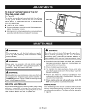
... product operation. LOCK NUT Fig. 56 MAINTENANCE WARNING: When servicing, use . GENERAL MAINTENANCE Avoid using solvents when cleaning plastic parts. LUBRICATION All of commercial solvents and may be difficult to damage from various types of the bearings in this warning could result in place. Try moving the fence from side-to remove dirt, dust, oil, grease, etc. ADJUSTMENTS TO CHECK THE TIGHTNESS OF THE RIP FENCE LOCKING LEVER...
... product operation. LOCK NUT Fig. 56 MAINTENANCE WARNING: When servicing, use . GENERAL MAINTENANCE Avoid using solvents when cleaning plastic parts. LUBRICATION All of commercial solvents and may be difficult to damage from various types of the bearings in this warning could result in place. Try moving the fence from side-to remove dirt, dust, oil, grease, etc. ADJUSTMENTS TO CHECK THE TIGHTNESS OF THE RIP FENCE LOCKING LEVER...

Operation Manual
Page 46
... sticky. Height/bevel adjusting hand-wheel Gears or screw post inside cabinet need Adjust positive stops. 45˚ cuts. Saw does not start. Circuit breaker is misaligned. Cord or switch is mounted backwards. Clean, sharpen, or replace blade. height/bevel adjusting handwheel. Motor labors in . Cause Blade is out of optional stand. Clamp screw is wrong type for rip cut . Cutting binds or burns work. Replace blade. Adjust clamp screw counterclockwise. Have the cord or switch replaced at rear. Blade is damaged. Remount blade. Blade not proper for...
... sticky. Height/bevel adjusting hand-wheel Gears or screw post inside cabinet need Adjust positive stops. 45˚ cuts. Saw does not start. Circuit breaker is misaligned. Cord or switch is mounted backwards. Clean, sharpen, or replace blade. height/bevel adjusting handwheel. Motor labors in . Cause Blade is out of optional stand. Clamp screw is wrong type for rip cut . Cutting binds or burns work. Replace blade. Adjust clamp screw counterclockwise. Have the cord or switch replaced at rear. Blade is damaged. Remount blade. Blade not proper for...


