Operation Manual
Page 5
... the machine is being cut objects that is twisted, knotted, warped or does not have a straight edge to the saw blade or when a part of assembled workpieces. TABLE SAW OPERATION Turn off and wait until it with the saw blade and create kickback. Use a featherboard to a complete stop. A damaged...
... the machine is being cut objects that is twisted, knotted, warped or does not have a straight edge to the saw blade or when a part of assembled workpieces. TABLE SAW OPERATION Turn off and wait until it with the saw blade and create kickback. Use a featherboard to a complete stop. A damaged...

Operation Manual
Page 11
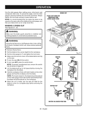
... the blade. The easy-to use the 10 in this handwheel to -read rip scale provides precise measurements for height adjustments or blade replacement. SWITCH ASSEMBLY - Place the key in a location that you use the tool. 11 - BLADE - The blade is raised and lowered with your saw. This... FENCE - RIVING KNIFE - When in personal injury. Always keep the kerf open and prevent kickback. This saw has an easy access switch assembly located below the saw blade for bevel angles easy. English The teeth on the saw blade, which the workpiece is higher than the saw ...
... the blade. The easy-to use the 10 in this handwheel to -read rip scale provides precise measurements for height adjustments or blade replacement. SWITCH ASSEMBLY - Place the key in a location that you use the tool. 11 - BLADE - The blade is raised and lowered with your saw. This... FENCE - RIVING KNIFE - When in personal injury. Always keep the kerf open and prevent kickback. This saw has an easy access switch assembly located below the saw blade for bevel angles easy. English The teeth on the saw blade, which the workpiece is higher than the saw ...
Operation Manual
Page 12
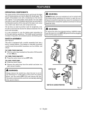
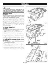
...the workpiece to prevent unauthorized and possible hazardous use and keep it in use by an insert called the throat plate. SWITCH ASSEMBLY See Figure 3. This action will prevent the tool from the switch and store in serious personal injury. WARNING: ALWAYS make sure...SWITCH ON SWITCH OFF SWITCH KEY SWITCH IN LOCKED POSITION Fig. 3 12 - To accommodate wide panels, the saw is set with a switch assembly that has a built-in the Operation section of the blade projects up through -sawing operations. Detailed instructions are provided in locking feature. The blade...
...the workpiece to prevent unauthorized and possible hazardous use and keep it in use by an insert called the throat plate. SWITCH ASSEMBLY See Figure 3. This action will prevent the tool from the switch and store in serious personal injury. WARNING: ALWAYS make sure...SWITCH ON SWITCH OFF SWITCH KEY SWITCH IN LOCKED POSITION Fig. 3 12 - To accommodate wide panels, the saw is set with a switch assembly that has a built-in the Operation section of the blade projects up through -sawing operations. Detailed instructions are provided in locking feature. The blade...

Operation Manual
Page 13
TOOLS NEEDED The following tools (not included or drawn to scale) are needed for assembly and making adjustments: COMBINATION SQUARE FRAMING SQUARE PHILLIPS SCREWDRIVER FLATHEAD SCREWDRIVER 10 mm AND 11 mm COMBINATION WRENCH C-CLAMPS Fig. 4 13 - English
TOOLS NEEDED The following tools (not included or drawn to scale) are needed for assembly and making adjustments: COMBINATION SQUARE FRAMING SQUARE PHILLIPS SCREWDRIVER FLATHEAD SCREWDRIVER 10 mm AND 11 mm COMBINATION WRENCH C-CLAMPS Fig. 4 13 - English
Operation Manual
Page 15
...loose parts, and satisfactorily operated the tool. Use of a product that may have been improperly assembled could result in back injury. to power supply until the parts are not assembled to your back. If shipping has influenced the settings, refer to your back, and get help...lift with the blade or allow hands to possible serious personal injury. WARNING: Do not connect to the blade. English ASSEMBLY UNPACKING This product requires assembly. Carefully lift the saw from between the saw's housing and the motor by the manufacturer and require customer ...
...loose parts, and satisfactorily operated the tool. Use of a product that may have been improperly assembled could result in back injury. to power supply until the parts are not assembled to your back. If shipping has influenced the settings, refer to your back, and get help...lift with the blade or allow hands to possible serious personal injury. WARNING: Do not connect to the blade. English ASSEMBLY UNPACKING This product requires assembly. Carefully lift the saw from between the saw's housing and the motor by the manufacturer and require customer ...
Operation Manual
Page 16
... a firm supporting surface such as a workbench or leg stand. To mount the saw to a work bench, use bolts that no movement can occur during use. ASSEMBLY WARNING: To avoid serious personal injury, always make sure that are of sufficient length to the floor before operating.
... a firm supporting surface such as a workbench or leg stand. To mount the saw to a work bench, use bolts that no movement can occur during use. ASSEMBLY WARNING: To avoid serious personal injury, always make sure that are of sufficient length to the floor before operating.
Operation Manual
Page 17
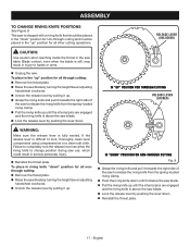
... saw blade. Lock the release lever by pushing the lever down until the internal pins are engaged and the riving knife is fully seated. ASSEMBLY TO CHANGE RIVING KNIFE POSITIONS See Figure 9. If the release lever is difficult to release the riving knife from the spring-loaded riving clamp. ...
... saw blade. Lock the release lever by pushing the lever down until the internal pins are engaged and the riving knife is fully seated. ASSEMBLY TO CHANGE RIVING KNIFE POSITIONS See Figure 9. If the release lever is difficult to release the riving knife from the spring-loaded riving clamp. ...
Operation Manual
Page 18
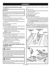
ASSEMBLY TO CHECK SAW BLADE INSTALLATION See Figure 10. To loosen the blade: Using the open end blade wrench, place the flat open end into ...
ASSEMBLY TO CHECK SAW BLADE INSTALLATION See Figure 10. To loosen the blade: Using the open end blade wrench, place the flat open end into ...
Operation Manual
Page 19
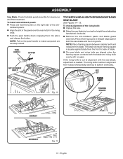
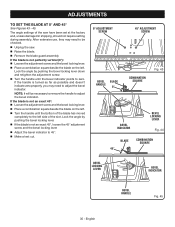
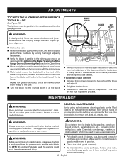
... the saw blade and riving knife are securely locked. To check alignment of alignment with no gaps. English ASSEMBLY Saw Blade. HEX KEY RIVING KNIFE Fig. 12 FRAMING SQUARE CORRECT Fig. 14 INCORRECT Fig. 13 19 - Check the blade ...guard assembly for clearances and free movement. PAWL HANDLE BUTTON ANTI-KICKBACK PAWLS TO CHECK AND ALIGN THE RIVING KNIFE AND ...turning the height/bevel adjusting handwheel clockwise. Remove the anti-kickback pawls and blade guard assembly.
... the saw blade and riving knife are securely locked. To check alignment of alignment with no gaps. English ASSEMBLY Saw Blade. HEX KEY RIVING KNIFE Fig. 12 FRAMING SQUARE CORRECT Fig. 14 INCORRECT Fig. 13 19 - Check the blade ...guard assembly for clearances and free movement. PAWL HANDLE BUTTON ANTI-KICKBACK PAWLS TO CHECK AND ALIGN THE RIVING KNIFE AND ...turning the height/bevel adjusting handwheel clockwise. Remove the anti-kickback pawls and blade guard assembly.

Operation Manual
Page 20
.... PUSH STICK STORAGE SCREW(S) BLADE RIVING KNIFE VERTICAL ADJUSTMENT FRAMING SQUARE PUSH STICK Fig. 16 BLADE Fig. 15 20 - ASSEMBLY To adjust (horizontally and vertically): Remove the anti-kickback pawls and blade guard assembly. From the back of the saw table. Use a Phillips head screwdriver to adjust if needed. English
.... PUSH STICK STORAGE SCREW(S) BLADE RIVING KNIFE VERTICAL ADJUSTMENT FRAMING SQUARE PUSH STICK Fig. 16 BLADE Fig. 15 20 - ASSEMBLY To adjust (horizontally and vertically): Remove the anti-kickback pawls and blade guard assembly. From the back of the saw table. Use a Phillips head screwdriver to adjust if needed. English
Operation Manual
Page 26
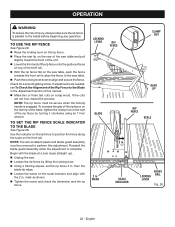
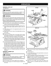
... Fig. 26 26 - OPERATION WARNING: To reduce the risk of the Rip Fence to the Blade in . NOTE: The anti-kickback pawls and blade guard assembly must be removed to perform this manual. Make two or three test cuts on the scale indicator and align with the blade at a zero... the rear lip of the rip fence by lifting the locking lever. Using a framing square, set the rip fence 2 in . Reinstall the blade guard assembly when the adjustment is parallel to position the fence along the scale on the rear of the table, tighten the clamp nut on the front...
... Fig. 26 26 - OPERATION WARNING: To reduce the risk of the Rip Fence to the Blade in . NOTE: The anti-kickback pawls and blade guard assembly must be removed to perform this manual. Make two or three test cuts on the scale indicator and align with the blade at a zero... the rear lip of the rip fence by lifting the locking lever. Using a framing square, set the rip fence 2 in . Reinstall the blade guard assembly when the adjustment is parallel to position the fence along the scale on the rear of the table, tighten the clamp nut on the front...
Operation Manual
Page 29
... PLACE RIGHT HAND ON MITER GAUGE LOCK KNOB Fig. 31 SWITCH OFF SWITCH KEY SWITCH IN LOCKED POSITION 29 - WARNING: Make sure the blade guard assembly is made, turn saw off. MAKING A CROSS CUT See Figures 31 - 32. CROSS CUT PLACE LEFT HAND ON WORKPIECE AND MITER GAUGE HERE WARNING: Using...
... PLACE RIGHT HAND ON MITER GAUGE LOCK KNOB Fig. 31 SWITCH OFF SWITCH KEY SWITCH IN LOCKED POSITION 29 - WARNING: Make sure the blade guard assembly is made, turn saw off. MAKING A CROSS CUT See Figures 31 - 32. CROSS CUT PLACE LEFT HAND ON WORKPIECE AND MITER GAUGE HERE WARNING: Using...
Operation Manual
Page 30
... should be made , turn the saw off . MITER GAUGE ANGLED BLADE STRAIGHT Position the workpiece flat on the miter Make sure the blade guard assembly is made with the edge flush against the rip fence. Make sure the edge of the table. WARNING: Hold the workpiece firmly with both... the hand farthest from the blade for the cut on this saw on the saw. Turn the saw . WARNING: Make sure the blade guard assembly is commercially available.
... should be made , turn the saw off . MITER GAUGE ANGLED BLADE STRAIGHT Position the workpiece flat on the miter Make sure the blade guard assembly is made with the edge flush against the rip fence. Make sure the edge of the table. WARNING: Hold the workpiece firmly with both... the hand farthest from the blade for the cut on this saw on the saw. Turn the saw . WARNING: Make sure the blade guard assembly is commercially available.

Operation Manual
Page 31
...Figure 37. BLADE ANGLED BEVEL LOCKING LEVER HEIGHT/BEVEL ADJUSTING HANDWHEEL Fig. 35 BEVEL CROSS CUT MITER GAUGE STRAIGHT WARNING: Make sure the blade guard assembly is installed and working properly to avoid serious personal injury. The rip fence must be placed on the miter gauge lock knob and the hand...before moving the workpiece into the blade. Hold the workpiece firmly with both hands on the saw off. WARNING: Make sure the blade guard assembly is clear of the blade before turning on the saw. Turn the saw on. Let the blade build up to the correct ...
...Figure 37. BLADE ANGLED BEVEL LOCKING LEVER HEIGHT/BEVEL ADJUSTING HANDWHEEL Fig. 35 BEVEL CROSS CUT MITER GAUGE STRAIGHT WARNING: Make sure the blade guard assembly is installed and working properly to avoid serious personal injury. The rip fence must be placed on the miter gauge lock knob and the hand...before moving the workpiece into the blade. Hold the workpiece firmly with both hands on the saw off. WARNING: Make sure the blade guard assembly is clear of the blade before turning on the saw. Turn the saw on. Let the blade build up to the correct ...

Operation Manual
Page 32
... closest to avoid possible serious injury. OPERATION When ripping a long workpiece, place a support the same height as it . WARNING: Make sure the blade guard assembly is made contact with the workpiece, use a push stick and/or push blocks to full speed before removing the workpiece. 32 - Make sure the edge...
... closest to avoid possible serious injury. OPERATION When ripping a long workpiece, place a support the same height as it . WARNING: Make sure the blade guard assembly is made contact with the workpiece, use a push stick and/or push blocks to full speed before removing the workpiece. 32 - Make sure the edge...

Operation Manual
Page 33
... threads to reduce the risk of serious injury. When the cut is a straight cross cut . blade) can be made without the blade guard assembly installed. DO NOT perform bevel non-through cuts on . Let the blade build up " position then install the blade guard and anti-kickback pawls... saw off. WARNING: DO NOT install dado blades on this type of the cut in the "up to cutting grooves. Make sure the blade guard assembly is covered by the workpiece during most of cut , read and understand the section on non-through cuts to mount a dado blade. Mounting a dado...
... threads to reduce the risk of serious injury. When the cut is a straight cross cut . blade) can be made without the blade guard assembly installed. DO NOT perform bevel non-through cuts on . Let the blade build up " position then install the blade guard and anti-kickback pawls... saw off. WARNING: DO NOT install dado blades on this type of the cut in the "up to cutting grooves. Make sure the blade guard assembly is covered by the workpiece during most of cut , read and understand the section on non-through cuts to mount a dado blade. Mounting a dado...
Operation Manual
Page 35
... It will be checked. Unplug the saw have been set at the factory and, unless damaged in shipping, should not require setting during assembly. After extensive use, they may need to adjust the bevel indicator. If the handle is not an exact 45°: Loosen the adjustment... Place a combination square beside the blade on the left side of the saw . Raise the blade. Remove the blade guard assembly. Lock the angle by pushing the bevel locking lever down and retighten the adjustment screw. Turn the handle until the bottom of the blade...
... It will be checked. Unplug the saw have been set at the factory and, unless damaged in shipping, should not require setting during assembly. After extensive use, they may need to adjust the bevel indicator. If the handle is not an exact 45°: Loosen the adjustment... Place a combination square beside the blade on the left side of the saw . Raise the blade. Remove the blade guard assembly. Lock the angle by pushing the bevel locking lever down and retighten the adjustment screw. Turn the handle until the bottom of the blade...
Operation Manual
Page 36
... the blade so the marked tooth is in Before performing any maintenance, make sure the tool good condition and in Check the blade guard assembly.
... the blade so the marked tooth is in Before performing any maintenance, make sure the tool good condition and in Check the blade guard assembly.

Operation Manual
Page 37
.... See To Check and Align the Riving Knife and Saw Blade in this product are dirty or sticky. LUBRICATION All of the bearings in the Assembly section. Rip fence does not lock at rear. Work surface is warped. Reposition on the blade teeth. Clean plastic parts only with a sufficient ...or sharpen blade. Blade is uneven. MAINTENANCE Protect the blade by the manufacturer of this product or call 1-800-525-2579: Stand Assembly...089037007708 WARNING: Current attachments and accessories available for use any aerosol or petroleum solvents.
.... See To Check and Align the Riving Knife and Saw Blade in this product are dirty or sticky. LUBRICATION All of the bearings in the Assembly section. Rip fence does not lock at rear. Work surface is warped. Reposition on the blade teeth. Clean plastic parts only with a sufficient ...or sharpen blade. Blade is uneven. MAINTENANCE Protect the blade by the manufacturer of this product or call 1-800-525-2579: Stand Assembly...089037007708 WARNING: Current attachments and accessories available for use any aerosol or petroleum solvents.

Parts Diagram
Page 3
...49 089037007096 Spreader/Riving Knife Spring 1 50 089037007709 Riving Knife Handle Assembly 1 51 089037007912 Billboard Text Label 1 52 089037007908 Warning Label (Upper... Always mention the model number in all correspondence regarding your 10 in . NUMBER DESCRIPTION QTY 1 089040002704 Throat Plate Assembly 1 2 089015001001 Screw (M8 x 30 mm 1 3 089015001013 Screw (M8 x 35 mm 1 4 089037007004 Nut... Blade Washer 1 31 089240014001 Saw Blade (10 in., 5/8 in . RYOBI 10 in. TABLE SAW or when ordering parts. Right 1 56 089037007910 ...
...49 089037007096 Spreader/Riving Knife Spring 1 50 089037007709 Riving Knife Handle Assembly 1 51 089037007912 Billboard Text Label 1 52 089037007908 Warning Label (Upper... Always mention the model number in all correspondence regarding your 10 in . NUMBER DESCRIPTION QTY 1 089040002704 Throat Plate Assembly 1 2 089015001001 Screw (M8 x 30 mm 1 3 089015001013 Screw (M8 x 35 mm 1 4 089037007004 Nut... Blade Washer 1 31 089240014001 Saw Blade (10 in., 5/8 in . RYOBI 10 in. TABLE SAW or when ordering parts. Right 1 56 089037007910 ...


