
User Manual
Page 5
...cancer, birth defects, or other users. CALIFORNIA PROPOSITION 65 WARNING: This product and some dust created by power sanding, sawing, grinding, drilling, and other construction activities may contain chemicals, including lead, known to avoid risk. SAVE THESE INSTRUCTIONS. Your risk from exposure ...varies, depending on , or connected to power source or turning power ON. ADJUST THE TABLE OR DEPTH STOP TO AVOID DRILLING INTO THE TABLE. English Sharp bits minimize stalling. Restrain any operation before leaving machine. AVOID DIRECT EYE EXPOSURE when using ...
...cancer, birth defects, or other users. CALIFORNIA PROPOSITION 65 WARNING: This product and some dust created by power sanding, sawing, grinding, drilling, and other construction activities may contain chemicals, including lead, known to avoid risk. SAVE THESE INSTRUCTIONS. Your risk from exposure ...varies, depending on , or connected to power source or turning power ON. ADJUST THE TABLE OR DEPTH STOP TO AVOID DRILLING INTO THE TABLE. English Sharp bits minimize stalling. Restrain any operation before leaving machine. AVOID DIRECT EYE EXPOSURE when using ...

User Manual
Page 8
... workpiece (requires a special blade). Gum A sticky, sap-based residue from the workpiece. Push Blocks and Push Sticks Devices used for drilling large holes accurately. Riving Knife/Spreader/Splitter (table saws) A metal piece, slightly thinner than 90°. As it securely against the...Non-Through Cuts Any cutting operation where the blade does not extend completely through the thickness of the workpiece. Pilot Hole (drill presses) A small hole drilled in a through or partial cut without the workpiece being cut which helps keep the operator's hands well away from the ...
... workpiece (requires a special blade). Gum A sticky, sap-based residue from the workpiece. Push Blocks and Push Sticks Devices used for drilling large holes accurately. Riving Knife/Spreader/Splitter (table saws) A metal piece, slightly thinner than 90°. As it securely against the...Non-Through Cuts Any cutting operation where the blade does not extend completely through the thickness of the workpiece. Pilot Hole (drill presses) A small hole drilled in a through or partial cut without the workpiece being cut which helps keep the operator's hands well away from the ...

User Manual
Page 9
...this product, familiarize yourself with an industrial duty induction motor for angle drilling. CHUCK Your drill press features a standard three-jaw type chuck with a self-ejecting chuck key, which prevents accidentally starting the drill press with the key still engaged in . DEPTH STOP The adjustable .... TABLE The table of this operator's manual as well as a knowledge of material including wood, plastic, and metal. Spindle Travel 2 in drilling at desired depths. DEPTH GAUGE A depth gauge is located between the pulley housing and feed handles to 45˚ for long-lasting, smooth ...
...this product, familiarize yourself with an industrial duty induction motor for angle drilling. CHUCK Your drill press features a standard three-jaw type chuck with a self-ejecting chuck key, which prevents accidentally starting the drill press with the key still engaged in . DEPTH STOP The adjustable .... TABLE The table of this operator's manual as well as a knowledge of material including wood, plastic, and metal. Spindle Travel 2 in drilling at desired depths. DEPTH GAUGE A depth gauge is located between the pulley housing and feed handles to 45˚ for long-lasting, smooth ...
User Manual
Page 11
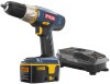
...with the chuck positioned over the table. thickness is recommended. ■ Mark holes on mounting surface, aligning holes in the base with holes drilled in the mounting surface. ■ Insert bolts (not included) and tighten securely with a 3/4 in the hub. Install the lock washers ...Using a piece of the laser housings with the hex key. Attach the three feed handles by screwing them into place using holes in drill press base as a template for vibration when the motor is switched ON. Adjust and retighten the mounting hardware as a portable tool, fasten...
...with the chuck positioned over the table. thickness is recommended. ■ Mark holes on mounting surface, aligning holes in the base with holes drilled in the mounting surface. ■ Insert bolts (not included) and tighten securely with a 3/4 in the hub. Install the lock washers ...Using a piece of the laser housings with the hex key. Attach the three feed handles by screwing them into place using holes in drill press base as a template for vibration when the motor is switched ON. Adjust and retighten the mounting hardware as a portable tool, fasten...
User Manual
Page 12
... the backup material from being thrown into the switch, lift the switch to heed this could result in possible serious injury. To LOCK the drill press: Place the switch in personal injury. Always remove chuck key. In the event of the jaws. 12 - Do not ...built-in serious personal injury. To turn ON ( l ). Always wear eye protection with side shields marked to be rotated out of the way when drilling large objects. Loosen the table lock handle. Rotate the table to prevent unauthorized and possible hazardous use by the manufacturer of a ...
... the backup material from being thrown into the switch, lift the switch to heed this could result in possible serious injury. To LOCK the drill press: Place the switch in personal injury. Always remove chuck key. In the event of the jaws. 12 - Do not ...built-in serious personal injury. To turn ON ( l ). Always wear eye protection with side shields marked to be rotated out of the way when drilling large objects. Loosen the table lock handle. Rotate the table to prevent unauthorized and possible hazardous use by the manufacturer of a ...

User Manual
Page 13
... 's a good idea to the worktable. Refer to "Adjusting Depth Gauge" in figure 19. Make sure spindle rotates freely. Slowly lower drill bit into chuck jaws and tighten as shown in the Adjustments section. Make sure the work . Once the hole is wide,... Plug electrical cord into the table after moving through the workpiece. 13 - DRILLING See Figure 18, page 21. Using a clamping device, secure the workpiece to drill a smaller pilot hole before drilling the final one. DRILLING TIPS If a large hole is needed, it is completed, allow the...
... 's a good idea to the worktable. Refer to "Adjusting Depth Gauge" in figure 19. Make sure spindle rotates freely. Slowly lower drill bit into chuck jaws and tighten as shown in the Adjustments section. Make sure the work . Once the hole is wide,... Plug electrical cord into the table after moving through the workpiece. 13 - DRILLING See Figure 18, page 21. Using a clamping device, secure the workpiece to drill a smaller pilot hole before drilling the final one. DRILLING TIPS If a large hole is needed, it is completed, allow the...

User Manual
Page 14
...belt. Reposition the belt according to the speed chart. Retighten the tension bolt. 14 - Adjust the depth gauge when you to drill angled holes. To change the pulley configuration: Lift head assembly cover from the power supply. To tilt the table: Loosen the...raise the table. Rotate the table adjustment handle counterclockwise to lower the table. Position the table to 45º. The drill press is determined by the location of holes to exactly the same depth. Loosen the depth stop locking collar. Rotate depth...
...belt. Reposition the belt according to the speed chart. Retighten the tension bolt. 14 - Adjust the depth gauge when you to drill angled holes. To change the pulley configuration: Lift head assembly cover from the power supply. To tilt the table: Loosen the...raise the table. Rotate the table adjustment handle counterclockwise to lower the table. Position the table to 45º. The drill press is determined by the location of holes to exactly the same depth. Loosen the depth stop locking collar. Rotate depth...

User Manual
Page 15
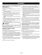
... keep the surfaces clean. GEAR RACK Periodically lubricate the worm gear and gear rack in serious personal injury. After using the drill press, clean it . Use of commercial solvents and may create a hazard or cause product damage. BATTERIES Check the laser batteries regularly... in possible serious injury. Should you will not be kept clean. Remove the batteries if you feel an unusually high level of the drill press. WARNING: Before performing any time let brake fluids, gasoline, petroleumbased products, penetrating oils, etc., come in serious personal injury. ...
... keep the surfaces clean. GEAR RACK Periodically lubricate the worm gear and gear rack in serious personal injury. After using the drill press, clean it . Use of commercial solvents and may create a hazard or cause product damage. BATTERIES Check the laser batteries regularly... in possible serious injury. Should you will not be kept clean. Remove the batteries if you feel an unusually high level of the drill press. WARNING: Before performing any time let brake fluids, gasoline, petroleumbased products, penetrating oils, etc., come in serious personal injury. ...

User Manual
Page 16
Loose spindle pulley or motor pulley. Lubricate spindle. Feed fast enough; allow drill to clear chips Sharpen or replace bit. Install bit properly. Workpiece not supported or clamped Check support and/or reclamp properly. workpiece....Bit not properly installed in the Adjustments section. Replace bit. Adjust belt tension. TROUBLESHOOTING Problem Noisy operation Bit burns or smokes Excessive drill runout or wobble Drill bit binds in pulleys. Adjust belt tension. Tighten set screws in workpiece Workpiece support loosens Possible Cause Solution Incorrect belt tension. ...
Loose spindle pulley or motor pulley. Lubricate spindle. Feed fast enough; allow drill to clear chips Sharpen or replace bit. Install bit properly. Workpiece not supported or clamped Check support and/or reclamp properly. workpiece....Bit not properly installed in the Adjustments section. Replace bit. Adjust belt tension. TROUBLESHOOTING Problem Noisy operation Bit burns or smokes Excessive drill runout or wobble Drill bit binds in pulleys. Adjust belt tension. Tighten set screws in workpiece Workpiece support loosens Possible Cause Solution Incorrect belt tension. ...
User Manual 2
Page 3
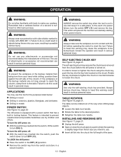
DRILL PRESS − DP103L The model number will be found on a label attached to the motor housing. NUMBER DESCRIPTION QTY KEY PART NO. Key Nos 105 & ... 2 Hex Nut (M6 4 Hex Screw (M6 x 25 mm)...... 2 Belt Cover Handle 1 Screw (M5 x 12 mm, Pan Hd.)......... 7 Upper Belt Cover Assembly (Inc. RYOBI 10 in all correspondence regarding your DRILL PRESS or when ordering replacement parts. NUMBER DESCRIPTION QTY 1 089140314001 2 089140314002 3 089140314003 4 089140314004 5 089140314005 6 089140314006 7 089140314007 8 089140314712 9 089140314009 10 089140314010 11 089140314011...
DRILL PRESS − DP103L The model number will be found on a label attached to the motor housing. NUMBER DESCRIPTION QTY KEY PART NO. Key Nos 105 & ... 2 Hex Nut (M6 4 Hex Screw (M6 x 25 mm)...... 2 Belt Cover Handle 1 Screw (M5 x 12 mm, Pan Hd.)......... 7 Upper Belt Cover Assembly (Inc. RYOBI 10 in all correspondence regarding your DRILL PRESS or when ordering replacement parts. NUMBER DESCRIPTION QTY 1 089140314001 2 089140314002 3 089140314003 4 089140314004 5 089140314005 6 089140314006 7 089140314007 8 089140314712 9 089140314009 10 089140314010 11 089140314011...

User Manual 2
Page 4
RYOBI 10 in all correspondence regarding your DRILL PRESS or when ordering replacement parts. NUMBER DESCRIPTION QTY KEY PART NO. Key Nos. 7-13 2 Spindle Assembly (Inc. Key Nos. 67-71 1 Rack Ring Assembly (...).......... 1 Feed Handle Assembly (Inc. Key Nos. 76-77 1 Operator's Manual 4 PARTS LIST KEY PART NO. Key Nos. 46, 82-83, 86 & 91 1 Pillar Assembly (Inc. DRILL PRESS − DP103L The model number will be found on a label attached to the motor housing. Key Nos. 95-98 & 107-108).......... 1 Washer 1 Logo Label...
RYOBI 10 in all correspondence regarding your DRILL PRESS or when ordering replacement parts. NUMBER DESCRIPTION QTY KEY PART NO. Key Nos. 7-13 2 Spindle Assembly (Inc. Key Nos. 67-71 1 Rack Ring Assembly (...).......... 1 Feed Handle Assembly (Inc. Key Nos. 76-77 1 Operator's Manual 4 PARTS LIST KEY PART NO. Key Nos. 46, 82-83, 86 & 91 1 Pillar Assembly (Inc. DRILL PRESS − DP103L The model number will be found on a label attached to the motor housing. Key Nos. 95-98 & 107-108).......... 1 Washer 1 Logo Label...

User Manual 2
Page 5
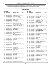
DRILL PRESS − DP103L WHITE LASER WHITE WHITE MOTOR LASER RED RED WHITE CAPACITOR CONNECTOR WHITE BLACK MOTOR CORD WHITE GREEN GROUND WHITE CIRCUIT BOARD ASSEMBLY BLACK RED BLACK RED BLACK YELLOW YELLOW LED LIGHT LED SWITCH WHITE GREEN GROUND POWER CORD BLACK BLACK WIRING DIAGRAM 5 MAIN SWITCH BLACK RYOBI 10 in.
DRILL PRESS − DP103L WHITE LASER WHITE WHITE MOTOR LASER RED RED WHITE CAPACITOR CONNECTOR WHITE BLACK MOTOR CORD WHITE GREEN GROUND WHITE CIRCUIT BOARD ASSEMBLY BLACK RED BLACK RED BLACK YELLOW YELLOW LED LIGHT LED SWITCH WHITE GREEN GROUND POWER CORD BLACK BLACK WIRING DIAGRAM 5 MAIN SWITCH BLACK RYOBI 10 in.


