Operation Manual
Page 2
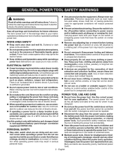
... batteries and chargers listed in any adjustments, changing accessories, or storing power tools. English WORK AREA SAFETY Keep work area clean and well lit. Unmodified plugs and matching outlets will reduce personal injuries. Prevent unintentional starting the power tool accidentally. Store idle power tools out of the reach of flammable liquids, gases or dust. Keep cord away from heat, oil, sharp edges or moving parts, breakage of electric...
... batteries and chargers listed in any adjustments, changing accessories, or storing power tools. English WORK AREA SAFETY Keep work area clean and well lit. Unmodified plugs and matching outlets will reduce personal injuries. Prevent unintentional starting the power tool accidentally. Store idle power tools out of the reach of flammable liquids, gases or dust. Keep cord away from heat, oil, sharp edges or moving parts, breakage of electric...
Operation Manual
Page 3
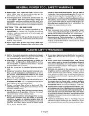
.... When battery pack is maintained. When servicing a power tool, use only identical replacement parts. Following this power tool. GENERAL POWER TOOL SAFETY WARNINGS Keep cutting tools sharp and clean. avoid contact. Use of unauthorized parts or failure to follow Maintenance instructions may create a risk of serious personal injury. Protect your hearing. Learn its applications and limitations, as well as a pilot light. Following this tool, loan them...
.... When battery pack is maintained. When servicing a power tool, use only identical replacement parts. Following this power tool. GENERAL POWER TOOL SAFETY WARNINGS Keep cutting tools sharp and clean. avoid contact. Use of unauthorized parts or failure to follow Maintenance instructions may create a risk of serious personal injury. Protect your hearing. Learn its applications and limitations, as well as a pilot light. Following this tool, loan them...
Operation Manual
Page 4
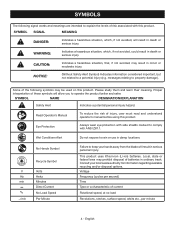
...risk associated with ANSI Z87.1. Proper interpretation of current Rotational speed, at no .../min Recycle Symbol Volts Hertz Minutes Direct Current No Load Speed Per Minute Failure to keep your local waste authority for ...Safety Alert Symbol) Indicates information considered important, but not related to comply with this product. Please study them and learn their meaning. Read Operator's Manual To reduce the risk of batteries in death or serious injury. Local, state or federal laws may prohibit disposal of injury, user must read and understand operator's manual before using...
...risk associated with ANSI Z87.1. Proper interpretation of current Rotational speed, at no .../min Recycle Symbol Volts Hertz Minutes Direct Current No Load Speed Per Minute Failure to keep your local waste authority for ...Safety Alert Symbol) Indicates information considered important, but not related to comply with this product. Please study them and learn their meaning. Read Operator's Manual To reduce the risk of batteries in death or serious injury. Local, state or federal laws may prohibit disposal of injury, user must read and understand operator's manual before using...
Operation Manual
Page 5
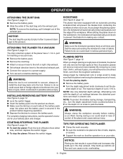
... assembled or with this product. Removing battery pack will point left (the handle will point right). Always wear eye protection with side shields marked to comply with tools to the same port selected by the manufacturer of lumber ADJUSTING THE EXHAUST DIRECTION See Figure 1, page 11. WARNING: Do not use any attachments or accessories not recommended by the exhaust direction lever...
... assembled or with this product. Removing battery pack will point left (the handle will point right). Always wear eye protection with side shields marked to comply with tools to the same port selected by the manufacturer of lumber ADJUSTING THE EXHAUST DIRECTION See Figure 1, page 11. WARNING: Do not use any attachments or accessories not recommended by the exhaust direction lever...
Operation Manual
Page 6
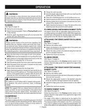
... lock-off button from the roughest workpiece. NOTE: Use only detented depth settings. Attempting cuts with each side of nails, staples, or screws. Support the work so that the area surrounding the kickstand is not connected to set the planing depth: Remove the battery pack. Turn the depth adjustment knob clockwise to vacuum, always reinstall the dust bag back onto the tool. TIPS FOR OPERATING THE PLANER Clamp...
... lock-off button from the roughest workpiece. NOTE: Use only detented depth settings. Attempting cuts with each side of nails, staples, or screws. Support the work so that the area surrounding the kickstand is not connected to set the planing depth: Remove the battery pack. Turn the depth adjustment knob clockwise to vacuum, always reinstall the dust bag back onto the tool. TIPS FOR OPERATING THE PLANER Clamp...
Operation Manual
Page 7
.... Clamp the work , using a slow, steady motion. Apply downward pressure to keep the rear section of the planer and tighten the knob bolt securely. Attach the edge guide to the bracket using the knob nut and the carriage head bolt (do not tighten). Adjust the edge guide to the desired width for the rabbet cut is 1/2 in contact with an adjustable edge guide for any operation; This...
.... Clamp the work , using a slow, steady motion. Apply downward pressure to keep the rear section of the planer and tighten the knob bolt securely. Attach the edge guide to the bracket using the knob nut and the carriage head bolt (do not tighten). Adjust the edge guide to the desired width for the rabbet cut is 1/2 in contact with an adjustable edge guide for any operation; This...
Operation Manual
Page 8
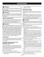
...; Depress the spring-loaded blade guard. 8 - When replacing the blades, use caution when loosening blade screws and handling and/or changing blades. WARNING: WARNING: Always wear heavy leather gloves and use recommended replacement blade only, RYOBI part number 039821001057. Clean the exhaust port and empty the dust bag regularly. Remove the battery pack. Remove the battery pack. Secure the planer in any of these types of blade holder after loosening blade securing screws, use . WARNING: Always...
...; Depress the spring-loaded blade guard. 8 - When replacing the blades, use caution when loosening blade screws and handling and/or changing blades. WARNING: WARNING: Always wear heavy leather gloves and use recommended replacement blade only, RYOBI part number 039821001057. Clean the exhaust port and empty the dust bag regularly. Remove the battery pack. Remove the battery pack. Secure the planer in any of these types of blade holder after loosening blade securing screws, use . WARNING: Always...
Operation Manual
Page 9
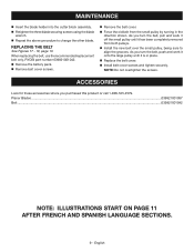
... small pulley by turning in place. Replace the belt cover. Install belt cover screws and tighten securely. English MAINTENANCE Insert the blade holder into the cutter block assembly. Retighten the three blade securing screws using the blade wrench. Repeat the above procedure to align the grooves. When replacing the belt, use the recommended replacement belt only, RYOBI part number 039821001042. Remove the battery pack. Remove belt cover screws. Remove the belt cover. Force...
... small pulley by turning in place. Replace the belt cover. Install belt cover screws and tighten securely. English MAINTENANCE Insert the blade holder into the cutter block assembly. Retighten the three blade securing screws using the blade wrench. Repeat the above procedure to align the grooves. When replacing the belt, use the recommended replacement belt only, RYOBI part number 039821001042. Remove the battery pack. Remove belt cover screws. Remove the belt cover. Force...
Parts Diagram
Page 3
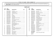
...Cutter Blade Wrench 1 039821001106 Edge Guide Assembly 1 019700001103 Dust Bag Assembly 1 940002196 Logo Label 1 941488205 Data Label 1 940930108 Kick Stand Label 1 941001427 Depth Adjustment Knob Label 1 039821001048 Knob Bolt 1 039821001051 Carriage Bolt (M5 x 12 mm 1 039821001052 Washer (M5 1 039821001053 Knob Nut 1 039821001056 Screw (M5 x 8 mm 4 019700001006 Compression Spring 1 019700001005 Lock-out Actuator 1 019700001010 Cover Piece 4 NOT SHOWN: 995000058 Operator's Manual (961152665) 12-20-16 (Rev:01) 3 MODEL NUMBER P611 The model number...
...Cutter Blade Wrench 1 039821001106 Edge Guide Assembly 1 019700001103 Dust Bag Assembly 1 940002196 Logo Label 1 941488205 Data Label 1 940930108 Kick Stand Label 1 941001427 Depth Adjustment Knob Label 1 039821001048 Knob Bolt 1 039821001051 Carriage Bolt (M5 x 12 mm 1 039821001052 Washer (M5 1 039821001053 Knob Nut 1 039821001056 Screw (M5 x 8 mm 4 019700001006 Compression Spring 1 019700001005 Lock-out Actuator 1 019700001010 Cover Piece 4 NOT SHOWN: 995000058 Operator's Manual (961152665) 12-20-16 (Rev:01) 3 MODEL NUMBER P611 The model number...
Parts Diagram
Page 4
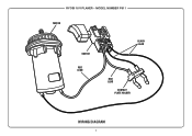
MODEL NUMBER P611 MOTOR SWITCH RED LEAD BLACK LEAD RED LEAD CONTACT PLATE HOLDER WIRING DIAGRAM 4 RYOBI 18 V PLANER -
MODEL NUMBER P611 MOTOR SWITCH RED LEAD BLACK LEAD RED LEAD CONTACT PLATE HOLDER WIRING DIAGRAM 4 RYOBI 18 V PLANER -


