

English Manual
Page 1
OPERATOR'S MANUAL 18 VOLT PLANER P610 Your planer has been engineered and manufactured to our high standard for your purchase. Thank you years of operation, and operator safety. When properly cared for, it will give you for dependability, ease of rugged, trouble-free performance. SAVE THIS MANUAL FOR FUTURE REFERENCE WARNING: To reduce the risk of injury, the user must read and understand the operator's manual before using this product.
OPERATOR'S MANUAL 18 VOLT PLANER P610 Your planer has been engineered and manufactured to our high standard for your purchase. Thank you years of operation, and operator safety. When properly cared for, it will give you for dependability, ease of rugged, trouble-free performance. SAVE THIS MANUAL FOR FUTURE REFERENCE WARNING: To reduce the risk of injury, the user must read and understand the operator's manual before using this product.
English Manual
Page 8
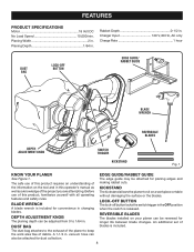
...DUST BAG LOCK-OFF BUTTON EDGE GUIDE/ RABBET GUIDE BLADE WRENCH REVERSIBLE BLADES DEPTH ADJUSTMENT KNOB SWITCH TRIGGER KICKSTAND Fig. 1 KNOW YOUR PLANER See Figure 1. EDGE GUIDE/RABBET GUIDE The edge guide may be attached for convenience in this product, familiarize yourself with all operating features... surface or the blades. DUST BAG The dust bag attaches to the exhaust of the project you are attempting. KICKSTAND The kickstand allows the planer to keep the work area free of blades is released. An additional set of debris. A 1-1/4 in . Planing Width 2 in . ...
...DUST BAG LOCK-OFF BUTTON EDGE GUIDE/ RABBET GUIDE BLADE WRENCH REVERSIBLE BLADES DEPTH ADJUSTMENT KNOB SWITCH TRIGGER KICKSTAND Fig. 1 KNOW YOUR PLANER See Figure 1. EDGE GUIDE/RABBET GUIDE The edge guide may be attached for convenience in this product, familiarize yourself with all operating features... surface or the blades. DUST BAG The dust bag attaches to the exhaust of the project you are attempting. KICKSTAND The kickstand allows the planer to keep the work area free of blades is released. An additional set of debris. A 1-1/4 in . Planing Width 2 in . ...
English Manual
Page 9
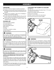
...INSTALLING/REMOVING THE DUST BAG See Figure 2. To install, slide the dust bag adaptor onto the chip exhaust on the right side of the planer has a 1-1/4 in a hazardous condition leading to possible serious personal injury. To remove the dust bag, grasp the adaptor and pull the dust... product has been shipped completely assembled. Carefully remove the tool and any accessories from the tool when assembling parts. PACKING LIST Planer (with this warning could cause serious personal injury, always remove the battery pack from the box. Wood particles are drawn up through the...
...INSTALLING/REMOVING THE DUST BAG See Figure 2. To install, slide the dust bag adaptor onto the chip exhaust on the right side of the planer has a 1-1/4 in a hazardous condition leading to possible serious personal injury. To remove the dust bag, grasp the adaptor and pull the dust... product has been shipped completely assembled. Carefully remove the tool and any accessories from the tool when assembling parts. PACKING LIST Planer (with this warning could cause serious personal injury, always remove the battery pack from the box. Wood particles are drawn up through the...
English Manual
Page 11
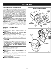
... will automatically disconnect when buttons are depressed. Remove the battery pack from the tool. NOTE: This situation only occurs when continuous use of the planer and latches into place and battery pack is hot, this will cause the green LED to come on , return battery pack to CHARGING A COOL BATTERY...
... will automatically disconnect when buttons are depressed. Remove the battery pack from the tool. NOTE: This situation only occurs when continuous use of the planer and latches into place and battery pack is hot, this will cause the green LED to come on , return battery pack to CHARGING A COOL BATTERY...

English Manual
Page 12
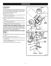
... Turn the depth adjustment knob clockwise to prevent the blade from either side, and then depress the switch trigger. To stop the planer: Release the switch trigger. PLANING DEPTH See Figure 8. When you begin planing a rough piece of the workpiece. NOTE: To protect the blades... 7. Failure to 0. Always begin your planing operation, the kickstand will automatically retract as it passes over the edge of material, the planer will only remove the high spots at your workbench, the kickstand will prevent the blade from the roughest workpiece. Therefore, switch should always...
... Turn the depth adjustment knob clockwise to prevent the blade from either side, and then depress the switch trigger. To stop the planer: Release the switch trigger. PLANING DEPTH See Figure 8. When you begin planing a rough piece of the workpiece. NOTE: To protect the blades... 7. Failure to 0. Always begin your planing operation, the kickstand will automatically retract as it passes over the edge of material, the planer will only remove the high spots at your workbench, the kickstand will prevent the blade from the roughest workpiece. Therefore, switch should always...

English Manual
Page 13
...to clear a blocked chip exhaust until both hands. Reverse or change the blades only as you always keep the rear section of the planer base in loss of control of blades on your right hand. Work moving during planing operation; WARNING: Be careful to heed this action... before making a cut . Keep a freshly charged battery available and replace the discharged battery when you have removed the battery. FRONT HANDLE OPERATING THE PLANER See Figure 9. Clamp the work securely. Support the work so that the front shoe is completely flat on the work. ...
...to clear a blocked chip exhaust until both hands. Reverse or change the blades only as you always keep the rear section of the planer base in loss of control of blades on your right hand. Work moving during planing operation; WARNING: Be careful to heed this action... before making a cut . Keep a freshly charged battery available and replace the discharged battery when you have removed the battery. FRONT HANDLE OPERATING THE PLANER See Figure 9. Clamp the work securely. Support the work so that the front shoe is completely flat on the work. ...
English Manual
Page 14
... a chamfering groove in the center position. Remove the battery pack from the tool. Attach the bracket to the desired side of the planer using the knob bolt. Attach the edge guide to the bracket using a slow, steady motion. Apply downward pressure to chamfer edges of...an adjustable edge guide for planing edges. Attach the edge guide to either side of the work surface. PLANING EDGES AND MAKING RABBET CUTS The planer comes with your left side for making a cut on good lumber, practice cutting on scrap lumber to determine the amount to be cut. &#...
... a chamfering groove in the center position. Remove the battery pack from the tool. Attach the bracket to the desired side of the planer using the knob bolt. Attach the edge guide to the bracket using a slow, steady motion. Apply downward pressure to chamfer edges of...an adjustable edge guide for planing edges. Attach the edge guide to either side of the work surface. PLANING EDGES AND MAKING RABBET CUTS The planer comes with your left side for making a cut on good lumber, practice cutting on scrap lumber to determine the amount to be cut. &#...

English Manual
Page 15
...the bracket to the left side of the cut . Tighten the retaining knob securely. Follow the directions in the Operating the Planer section earlier in Operating the Planer. The maximum depth of the rabbet cut is determined by placing the lock-off button in . ATTACHING THE EDGE GUIDE FOR MAKING ...RABBET CUTS Lock the switch by the depth of the planer using the knob bolt. Attach the edge guide loosely to the bracket using the knob nut and the carriage head bolt. Adjust ...
...the bracket to the left side of the cut . Tighten the retaining knob securely. Follow the directions in the Operating the Planer section earlier in Operating the Planer. The maximum depth of the rabbet cut is determined by placing the lock-off button in . ATTACHING THE EDGE GUIDE FOR MAKING ...RABBET CUTS Lock the switch by the depth of the planer using the knob bolt. Attach the edge guide loosely to the bracket using the knob nut and the carriage head bolt. Adjust ...
English Manual
Page 17
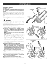
... is centered into the slot of becoming dull, chipped, or damaged in any sawdust or wood chips from the tool. Secure the planer in the same orientation as how the tapered edge of a screwdriver. Remove the old blade from the blade holder. The tapered edge...loosening the screws, use the recommended replacement blades only (Part No. 671798001). MAINTENANCE CHANGING BLADES See Figures 14 - 16. If the blades in the planer show signs of the blade holder. Use a screwdriver to change the other side can be in an upside-down position. Loosen...
... is centered into the slot of becoming dull, chipped, or damaged in any sawdust or wood chips from the tool. Secure the planer in the same orientation as how the tapered edge of a screwdriver. Remove the old blade from the blade holder. The tapered edge...loosening the screws, use the recommended replacement blades only (Part No. 671798001). MAINTENANCE CHANGING BLADES See Figures 14 - 16. If the blades in the planer show signs of the blade holder. Use a screwdriver to change the other side can be in an upside-down position. Loosen...
English Manual
Page 19
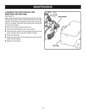
.... Unzip the dust bag. Empty all debris from the chip exhaust. Clean the build-up in the chip exhaust. After using the planer for an extended period of time or when planing wet or green lumber, chips may build up from the chip exhaust port with a small piece...
.... Unzip the dust bag. Empty all debris from the chip exhaust. Clean the build-up in the chip exhaust. After using the planer for an extended period of time or when planing wet or green lumber, chips may build up from the chip exhaust port with a small piece...
English Manual
Page 20
OPERATOR'S MANUAL 18 VOLT PLANER P610 WARNING: Some dust created by power sanding, sawing, grinding, drilling,..., • crystalline silica from bricks and cement and other reproductive harm. Please call or visit. The model number of Ryobi Limited used under license. 983000-936 1-30-06 (REV:00) ONE WORLD TECHNOLOGIES, INC. 1428 Pearman Dairy Road,...HOW TO ORDER REPAIR PARTS When ordering repair parts, always give the following information: • MODEL NUMBER P610 • SERIAL NUMBER Ryobi® is a registered trademark of this tool will be found on how often you call 1-800-...
OPERATOR'S MANUAL 18 VOLT PLANER P610 WARNING: Some dust created by power sanding, sawing, grinding, drilling,..., • crystalline silica from bricks and cement and other reproductive harm. Please call or visit. The model number of Ryobi Limited used under license. 983000-936 1-30-06 (REV:00) ONE WORLD TECHNOLOGIES, INC. 1428 Pearman Dairy Road,...HOW TO ORDER REPAIR PARTS When ordering repair parts, always give the following information: • MODEL NUMBER P610 • SERIAL NUMBER Ryobi® is a registered trademark of this tool will be found on how often you call 1-800-...
Repair Sheet
Page 3
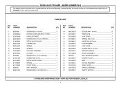
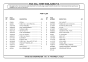
RYOBI 18 VOLT PLANER - PART NUMBER 18 660279007 19 631423001 20 ...ASSEMBLY 1 WIND COVER 1 HANDLE ASSEMBLY 1 SAFETY BUTTON 1 * STANDARD HARDWARE ITEM - Always mention the model number in all correspondence regarding your PLANER or when ordering repair parts. PART NUMBER 1 6620606 2 200392002 3 513570002 4 660206018 5 514506001 6 690541001 7 690542001 8 513702001 9 200078027... * SCREW (M8 X 9 mm HEX SOC 1 KEY NO. PARTS LIST KEY NO. MODEL NUMBER P610 The model number will be found on a plate attached to the motor housing. MAY BE PURCHASED LOCALLY 3
RYOBI 18 VOLT PLANER - PART NUMBER 18 660279007 19 631423001 20 ...ASSEMBLY 1 WIND COVER 1 HANDLE ASSEMBLY 1 SAFETY BUTTON 1 * STANDARD HARDWARE ITEM - Always mention the model number in all correspondence regarding your PLANER or when ordering repair parts. PART NUMBER 1 6620606 2 200392002 3 513570002 4 660206018 5 514506001 6 690541001 7 690542001 8 513702001 9 200078027... * SCREW (M8 X 9 mm HEX SOC 1 KEY NO. PARTS LIST KEY NO. MODEL NUMBER P610 The model number will be found on a plate attached to the motor housing. MAY BE PURCHASED LOCALLY 3
Repair Sheet
Page 4
... X 25 mm PAN HD 1 SWITCH ASSEMBLY 1 EDGE GUIDE ASSEMBLY 1 WARNING LABEL 1 * HEX KEY (5/32 in all correspondence regarding your PLANER or when ordering repair parts. HD 4 STRAIGHT PLANER BLADE 4 SPRING 4 DRIVE PULLEY 1 BALL BEARING (688Z 1 KEY NO. MODEL NUMBER P610 The model number will be found on a plate attached to the motor housing...
... X 25 mm PAN HD 1 SWITCH ASSEMBLY 1 EDGE GUIDE ASSEMBLY 1 WARNING LABEL 1 * HEX KEY (5/32 in all correspondence regarding your PLANER or when ordering repair parts. HD 4 STRAIGHT PLANER BLADE 4 SPRING 4 DRIVE PULLEY 1 BALL BEARING (688Z 1 KEY NO. MODEL NUMBER P610 The model number will be found on a plate attached to the motor housing...

Repair Sheet
Page 5
MODEL NUMBER P610 MOTOR SWITCH BLACK LEAD RED LEAD RED LEAD CONTACT PLATE HOLDER WIRING DIAGRAM 5 RYOBI 18 VOLT PLANER -
MODEL NUMBER P610 MOTOR SWITCH BLACK LEAD RED LEAD RED LEAD CONTACT PLATE HOLDER WIRING DIAGRAM 5 RYOBI 18 VOLT PLANER -


