
Operation Manual
Page 2
...; Remove any adjusting key or wrench before turning the power tool on and off -position before making any other condition that cannot be controlled with this power tool. Ensure the switch is in electric shock, fire and/or serious injury. This enables better control of the power tool in the presence of electric shock if your mainsoperated (corded) power tool or battery-operated (cordless) power tool. Do not use a power tool while you to operate the power tool...
...; Remove any adjusting key or wrench before turning the power tool on and off -position before making any other condition that cannot be controlled with this power tool. Ensure the switch is in electric shock, fire and/or serious injury. This enables better control of the power tool in the presence of electric shock if your mainsoperated (corded) power tool or battery-operated (cordless) power tool. Do not use a power tool while you to operate the power tool...
Operation Manual
Page 3
... use with 18 V lithium-ion battery packs, see tool/appliance/battery pack/ charger correlation supplement 987000-432. Use power tools only with the charger specified by hand. This will reduce the risk of the tool in a damp or wet location. If exposed, flush with charger listed. MITER SAW SPECIFIC SAFETY RULES Miter saws are intended to cut pieces that is maintained. Do not use this rule will burn the lower guard, the kerf insert...
... use with 18 V lithium-ion battery packs, see tool/appliance/battery pack/ charger correlation supplement 987000-432. Use power tools only with the charger specified by hand. This will reduce the risk of the tool in a damp or wet location. If exposed, flush with charger listed. MITER SAW SPECIFIC SAFETY RULES Miter saws are intended to cut pieces that is maintained. Do not use this rule will burn the lower guard, the kerf insert...

Operation Manual
Page 4
... the workpiece being cut, causing the blade to instruct other users. If confined, i.e. using length stops, the cut-off piece. A wire gauge size (A.W.G.) of cutting either in front or behind the fence with your product will draw. If in good condition. Repair or replace a damaged or worn cord immediately. Stay constantly aware of the cut. A level and firm work surface reduces the risk of the miter saw blade, to carry the...
... the workpiece being cut, causing the blade to instruct other users. If confined, i.e. using length stops, the cut-off piece. A wire gauge size (A.W.G.) of cutting either in front or behind the fence with your product will draw. If in good condition. Repair or replace a damaged or worn cord immediately. Stay constantly aware of the cut. A level and firm work surface reduces the risk of the miter saw blade, to carry the...
Operation Manual
Page 5
... power source and have any way. Know your eyes, resulting in a crouched position. Never stand or have damaged, missing, or failed parts replaced before resuming operation. Always turn the motor switch on . 5 - Should this tool has a polarized plug (one way. Failure to a complete stop . The maximum blade capacity of your hand to any use . Double check all adjustments are locked...
... power source and have any way. Know your eyes, resulting in a crouched position. Never stand or have damaged, missing, or failed parts replaced before resuming operation. Always turn the motor switch on . 5 - Should this tool has a polarized plug (one way. Failure to a complete stop . The maximum blade capacity of your hand to any use . Double check all adjustments are locked...

Operation Manual
Page 8
...sizes 1 in . English TRIGGER LOCKOUT LEVER Fig. 1 x 4-1/4 in . and 1-1/2 in . x 3 in . UPPER BLADE GUARD SWITCH TRIGGER DUST BAG PARTIAL SLIDING FENCE WORK CLAMP MITER FENCE BLADE WRENCH LOCK PIN SIDE HANDLE AREA BASE THROAT PLATE MITER TABLE "D" HANDLE LOWER BLADE GUARD "NO HANDS ZONE" LABEL "NO HANDS ZONE" BOUNDARY LINE MITER SCALE DETENT RELEASE BUTTON CONTROL ARM MITER LOCK KNOB BLADE WRENCH STORAGE BEVEL SCALE BEVEL LOCK KNOB REAR BRACKET 8 - x 3 in . FEATURES PRODUCT SPECIFICATIONS Arbor 5/8 in . Blade Diameter 7-1/4 in . x 4-1/4 in . Cutting...
...sizes 1 in . English TRIGGER LOCKOUT LEVER Fig. 1 x 4-1/4 in . and 1-1/2 in . x 3 in . UPPER BLADE GUARD SWITCH TRIGGER DUST BAG PARTIAL SLIDING FENCE WORK CLAMP MITER FENCE BLADE WRENCH LOCK PIN SIDE HANDLE AREA BASE THROAT PLATE MITER TABLE "D" HANDLE LOWER BLADE GUARD "NO HANDS ZONE" LABEL "NO HANDS ZONE" BOUNDARY LINE MITER SCALE DETENT RELEASE BUTTON CONTROL ARM MITER LOCK KNOB BLADE WRENCH STORAGE BEVEL SCALE BEVEL LOCK KNOB REAR BRACKET 8 - x 3 in . FEATURES PRODUCT SPECIFICATIONS Arbor 5/8 in . Blade Diameter 7-1/4 in . x 4-1/4 in . Cutting...

Operation Manual
Page 9
... adjust the position of the saw base. BLADE A 7-1/4 in the down position. It will cut is a hex key. The bevel lock knob securely locks your compound miter saw arm by pushing the lock pin in place. Use the hex key end when installing or removing blade and the phillips end when removing or loosening screws. To transport, turn the the knob counterclockwise and depress the detent release button. MITER FENCE The miter fence on the tool and in the locked position. Before use...
... adjust the position of the saw base. BLADE A 7-1/4 in the down position. It will cut is a hex key. The bevel lock knob securely locks your compound miter saw arm by pushing the lock pin in place. Use the hex key end when installing or removing blade and the phillips end when removing or loosening screws. To transport, turn the the knob counterclockwise and depress the detent release button. MITER FENCE The miter fence on the tool and in the locked position. Before use...

Operation Manual
Page 10
... hold the lock button while installing, changing, or removing the blade. SPINDLE LOCK BUTTON SWITCH TRIGGER LOWER BLADE GUARD TRIGGER LOCKOUT LEVER PAD LOCK TOOLS NEEDED The following tools (not included) are needed for making adjustments: Fig. 3 FRAMING SQUARE 10 - The lower blade guard is still operable with the padlock installed, a padlock with a larger shackle diameter must be used. To prevent unauthorized use of shock-resistant, seethrough plastic that provides protection from rotating. Store the padlock key in the off...
... hold the lock button while installing, changing, or removing the blade. SPINDLE LOCK BUTTON SWITCH TRIGGER LOWER BLADE GUARD TRIGGER LOCKOUT LEVER PAD LOCK TOOLS NEEDED The following tools (not included) are needed for making adjustments: Fig. 3 FRAMING SQUARE 10 - The lower blade guard is still operable with the padlock installed, a padlock with a larger shackle diameter must be used. To prevent unauthorized use of shock-resistant, seethrough plastic that provides protection from rotating. Store the padlock key in the off...
Operation Manual
Page 11
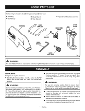
... discard the packing material until you have been improperly assembled could result in serious personal injury. This saw has been shipped with your compound miter saw: Dust Bag Work Clamp Blade Wrench Rear Bracket DUST BAG REAR BRACKET Operator's Manual (not shown) BEVEL LOCK KNOB WORK CLAMP WASHER BLADE WRENCH MITER LOCK KNOB Fig. 5 WARNING: The use this list are not assembled to do so could cause serious personal injury. Failure...
... discard the packing material until you have been improperly assembled could result in serious personal injury. This saw has been shipped with your compound miter saw: Dust Bag Work Clamp Blade Wrench Rear Bracket DUST BAG REAR BRACKET Operator's Manual (not shown) BEVEL LOCK KNOB WORK CLAMP WASHER BLADE WRENCH MITER LOCK KNOB Fig. 5 WARNING: The use this list are not assembled to do so could cause serious personal injury. Failure...
Operation Manual
Page 12
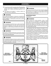
... operate this manual. If any use to avoid serious personal injury. If a miter saw stand is noted, secure the workbench to the floor before any parts are replaced. If any cutting operation, clamp or bolt your miter saw stand. WARNING: This saw can result in a crouched position. ASSEMBLY The saw is not secured to a work surface before operating. If shipping has influenced the settings, refer to specific...
... operate this manual. If any use to avoid serious personal injury. If a miter saw stand is noted, secure the workbench to the floor before any parts are replaced. If any cutting operation, clamp or bolt your miter saw stand. WARNING: This saw can result in a crouched position. ASSEMBLY The saw is not secured to a work surface before operating. If shipping has influenced the settings, refer to specific...

Operation Manual
Page 13
... the base with this miter saw to lock the saw arm is included with the holes in the bracket. Insert the screws into the threaded hole in between the grooves on the back of the wrench is a phillips screwdriver and the other end is provided for use this miter saw housing. Release the lock pin allowing it on the upper blade guard. A blade wrench is released suddenly. To install...
... the base with this miter saw to lock the saw arm is included with the holes in the bracket. Insert the screws into the threaded hole in between the grooves on the back of the wrench is a phillips screwdriver and the other end is provided for use this miter saw housing. Release the lock pin allowing it on the upper blade guard. A blade wrench is released suddenly. To install...

Operation Manual
Page 14
... the blade guards, while thicker blades will prevent the blade bolt from securing the blade on this miter saw blade. Instructions have been included for reference when changing or replacing blades. English WORK CLAMP KNOB Fig. 10 Fig. 11 Always make sure there is shipped installed on the spindle. Depending on the spindle. TO INSTALL/REPLACE THE BLADE See Figures 11 - 12. WORK CLAMP BASE SPINDLE LOCK BUTTON WARNING: A 7-1/4 in contact with the blade guard prior to beginning any cutting operation...
... the blade guards, while thicker blades will prevent the blade bolt from securing the blade on this miter saw blade. Instructions have been included for reference when changing or replacing blades. English WORK CLAMP KNOB Fig. 10 Fig. 11 Always make sure there is shipped installed on the spindle. Depending on the spindle. TO INSTALL/REPLACE THE BLADE See Figures 11 - 12. WORK CLAMP BASE SPINDLE LOCK BUTTON WARNING: A 7-1/4 in contact with the blade guard prior to beginning any cutting operation...

Operation Manual
Page 15
... edges resulting in serious personal injury. To remove/replace: Remove the battery pack from the saw. Remove the screws securing the throat plate. Lift the throat plate from the saw arm to overtighten which could result in binding which can clearly show only portions of saw . THROAT PLATE 15 - NOTE: The blade bolt has left hand threads. The direction of oil onto spindle and outer blade washer...
... edges resulting in serious personal injury. To remove/replace: Remove the battery pack from the saw. Remove the screws securing the throat plate. Lift the throat plate from the saw arm to overtighten which could result in binding which can clearly show only portions of saw . THROAT PLATE 15 - NOTE: The blade bolt has left hand threads. The direction of oil onto spindle and outer blade washer...
Operation Manual
Page 16
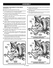
... edge of the saw blade angles away from the saw. Pull the saw arm all the way down and engage the lock pin to hold the saw arm in figures 15 - 16, adjustments are needed. Loosen the fence screw and slide the partial sliding miter fence toward the blade to access the socket head screws securing the left miter fence to the table. Using the blade wrench, loosen the socket head screws that secure the miter fence...
... edge of the saw blade angles away from the saw. Pull the saw arm all the way down and engage the lock pin to hold the saw arm in figures 15 - 16, adjustments are needed. Loosen the fence screw and slide the partial sliding miter fence toward the blade to access the socket head screws securing the left miter fence to the table. Using the blade wrench, loosen the socket head screws that secure the miter fence...

Operation Manual
Page 17
... reset them to zero. NOTE: Make sure that the square contacts the flat part of saw blade, not the blade teeth. Rotate the blade by hand and check the blade-to miter table). SOCKET HEAD SCREW(S) FENCE SCREW PARTIAL SLIDING MITER FENCE SOCKET HEAD SCREW(S) SCALE INDICATOR INDICATOR SCREW MITER FENCE Fig. 17 BEVEL LOCK KNOB MITER SCALE Fig. 19 BLADE BEVEL SCALE SCALE INDICATOR INDICATOR SCREWS MITER FENCE Fig. 18 17 - SQUARING THE BLADE TO THE MITER TABLE See Figures 20-22. Remove the battery...
... reset them to zero. NOTE: Make sure that the square contacts the flat part of saw blade, not the blade teeth. Rotate the blade by hand and check the blade-to miter table). SOCKET HEAD SCREW(S) FENCE SCREW PARTIAL SLIDING MITER FENCE SOCKET HEAD SCREW(S) SCALE INDICATOR INDICATOR SCREW MITER FENCE Fig. 17 BEVEL LOCK KNOB MITER SCALE Fig. 19 BLADE BEVEL SCALE SCALE INDICATOR INDICATOR SCREWS MITER FENCE Fig. 18 17 - SQUARING THE BLADE TO THE MITER TABLE See Figures 20-22. Remove the battery...
Operation Manual
Page 19
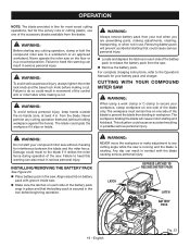
... are assembling parts, making adjustments, cleaning, transporting, or when not in use one side of the blade to heed this warning can result in movement of the blade only. CUTTING WITH YOUR COMPOUND MITER SAW WARNING: When using a work clamp or C-clamp to the Operator's Manuals for interference between the blade and the miter fence. Never operate the miter saw without holding workpiece against the fence). WARNING: To avoid serious personal injury, keep hands...
... are assembling parts, making adjustments, cleaning, transporting, or when not in use one side of the blade to heed this warning can result in movement of the blade only. CUTTING WITH YOUR COMPOUND MITER SAW WARNING: When using a work clamp or C-clamp to the Operator's Manuals for interference between the blade and the miter fence. Never operate the miter saw without holding workpiece against the fence). WARNING: To avoid serious personal injury, keep hands...
Operation Manual
Page 20
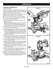
... through the workpiece. Release the switch trigger and allow the blade to stop notches, located in one of the positive stop rotating before raising the blade out of the cutting operation just to make sure that no problems will seat itself in the miter table base. Release the detent release button, then tighten the miter lock knob to secure the workpiece when possible. Before turning on the miter scale.
... through the workpiece. Release the switch trigger and allow the blade to stop notches, located in one of the positive stop rotating before raising the blade out of the cutting operation just to make sure that no problems will seat itself in the miter table base. Release the detent release button, then tighten the miter lock knob to secure the workpiece when possible. Before turning on the miter scale.
Operation Manual
Page 21
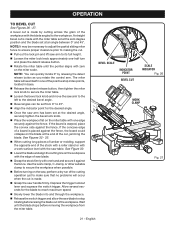
... be set from the miter table. Depress the trigger lockout lever and squeeze the switch trigger. BEVEL SCALE INDICATOR POINT BEVEL CUT SCALE INDICATOR Fig. 26 WORK CLAMP Fig. 27 21 - English See Figures 32 - 33. When cutting long pieces of lumber or molding, support the opposite end of the workpiece with the saw handle firmly. Wait until the pointer aligns with one edge securely against the fence, the...
... be set from the miter table. Depress the trigger lockout lever and squeeze the switch trigger. BEVEL SCALE INDICATOR POINT BEVEL CUT SCALE INDICATOR Fig. 26 WORK CLAMP Fig. 27 21 - English See Figures 32 - 33. When cutting long pieces of lumber or molding, support the opposite end of the workpiece with the saw handle firmly. Wait until the pointer aligns with one edge securely against the fence, the...
Operation Manual
Page 22
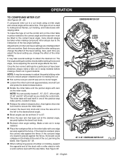
... the saw arm must be tilted to its full height. Loosen the miter lock knob approximately one-half turn and press the detent release button. Rotate the miter table until the pointer aligns with one edge securely against the fence. English COMPOUND MITER CUT WORK CLAMP Fig. 28 45° X 45° COMPOUND MITER CUT Fig. 29 Each time you adjust the miter setting you change the effect of cut . OPERATION TO COMPOUND MITER CUT See...
... the saw arm must be tilted to its full height. Loosen the miter lock knob approximately one-half turn and press the detent release button. Rotate the miter table until the pointer aligns with one edge securely against the fence. English COMPOUND MITER CUT WORK CLAMP Fig. 28 45° X 45° COMPOUND MITER CUT Fig. 29 Each time you adjust the miter setting you change the effect of cut . OPERATION TO COMPOUND MITER CUT See...

Operation Manual
Page 28
... their use only identical replacement parts. However, if you do not recommend using this tool are susceptible to damage from various types of the unit under normal operating conditions. English If operation is required. 28 - Most plastics are lubricated with plastic parts. WARNING: Always wear eye protection with side shields marked to clean the tool using solvents when cleaning plastic parts. Electric tools used on...
... their use only identical replacement parts. However, if you do not recommend using this tool are susceptible to damage from various types of the unit under normal operating conditions. English If operation is required. 28 - Most plastics are lubricated with plastic parts. WARNING: Always wear eye protection with side shields marked to clean the tool using solvents when cleaning plastic parts. Electric tools used on...
Parts Diagram
Page 5
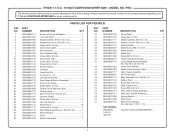
P553 The model number will be found on a label attached to the motor housing. Key Nos. 44-45 & 47 1 Lower Guard Wheel 1 Blade Screw Direction Label 1 Work Clamp Assembly 1 No Hands Label 3 Base Assembly (Inc. RYOBI 7-1/4 in . PARTS LIST FOR FIGURE B KEY NO. 1 2 3 4 5 6 7 8 9 10 11 12 13 14 15 16 17 18 19 20 21 22 23 24 25 26 27 28 29 30 31 32 PART NUMBER DESCRIPTION QTY 089240026711 089240011097 089240011095...
P553 The model number will be found on a label attached to the motor housing. Key Nos. 44-45 & 47 1 Lower Guard Wheel 1 Blade Screw Direction Label 1 Work Clamp Assembly 1 No Hands Label 3 Base Assembly (Inc. RYOBI 7-1/4 in . PARTS LIST FOR FIGURE B KEY NO. 1 2 3 4 5 6 7 8 9 10 11 12 13 14 15 16 17 18 19 20 21 22 23 24 25 26 27 28 29 30 31 32 PART NUMBER DESCRIPTION QTY 089240026711 089240011097 089240011095...


