

User Manual
Page 2
...; Remove any adjustments, changing accessories, or storing power tools. English The correct power tool will increase the risk of the power tool in unexpected situations. Dress properly. This enables better control of these instructions to rain or wet conditions. Keep proper footing and balance at the rate for your mains-operated (corded) power tool or battery-operated (cordless) power tool. Use the correct power tool for which may result in any adapter plugs...
...; Remove any adjustments, changing accessories, or storing power tools. English The correct power tool will increase the risk of the power tool in unexpected situations. Dress properly. This enables better control of these instructions to rain or wet conditions. Keep proper footing and balance at the rate for your mains-operated (corded) power tool or battery-operated (cordless) power tool. Use the correct power tool for which may result in any adapter plugs...

User Manual
Page 3
... own cord. To reduce the risk of injury, user must be within the capacity rating of control. Do not use only identical replacement parts. Cutting accessory contacting a ²live² wire may create a hazard and cause personal injury. Do not use face shield, safety goggles or safety glasses. The eye protection must read instruction manual. When servicing a power tool, use a damaged accessory. The spinning accessory may...
... own cord. To reduce the risk of injury, user must be within the capacity rating of control. Do not use only identical replacement parts. Cutting accessory contacting a ²live² wire may create a hazard and cause personal injury. Do not use face shield, safety goggles or safety glasses. The eye protection must read instruction manual. When servicing a power tool, use a damaged accessory. The spinning accessory may...
User Manual
Page 4
... load to protect operator from larger power tools. SPECIFIC SAFETY RULES Do not operate the power tool near the rotating accessory. For example, if an abrasive wheel is snagged or pinched by the brush even during start-up. Flanges for cut -off wheels may cause them to resist kickback forces. SAFETY WARNINGS SPECIFIC FOR SANDING OPERATIONS Do not use auxiliary handle, if provided, for the selected wheel. SAFETY WARNINGS SPECIFIC FOR WIRE BRUSH OPERATIONS...
... load to protect operator from larger power tools. SPECIFIC SAFETY RULES Do not operate the power tool near the rotating accessory. For example, if an abrasive wheel is snagged or pinched by the brush even during start-up. Flanges for cut -off wheels may cause them to resist kickback forces. SAFETY WARNINGS SPECIFIC FOR SANDING OPERATIONS Do not use auxiliary handle, if provided, for the selected wheel. SAFETY WARNINGS SPECIFIC FOR WIRE BRUSH OPERATIONS...

User Manual
Page 5
... tool. Your risk from lumber before using an extension cord, be replaced only by the manufacturer or by an authorized service center. A wire gauge size (A.W.G.) of power and overheating. Inspect for and remove all nails from exposure to filter out microscopic particles. 5 - Check for an extension cord 50 feet or less in good condition. The smaller the gauge number, the heavier the cord. A guard...
... tool. Your risk from lumber before using an extension cord, be replaced only by the manufacturer or by an authorized service center. A wire gauge size (A.W.G.) of power and overheating. Inspect for and remove all nails from exposure to filter out microscopic particles. 5 - Check for an extension cord 50 feet or less in good condition. The smaller the gauge number, the heavier the cord. A guard...

User Manual
Page 6
...situation, which, if not avoided, may result in death or serious injury. Some of injury, user must read and understand operator's manual before using this product. Read Operator's Manual To reduce the risk of the following signal words and meanings are intended to an injury hazard...Proper interpretation of current Rotational speed, at no .../min Wet Conditions Alert Volts Amperes Hertz Watt Minutes Alternating Current No Load Speed Class II Tool Per Minute Do not expose to operate the product better and safer. NOTICE: (Without Safety Alert Symbol) Indicates important information...
...situation, which, if not avoided, may result in death or serious injury. Some of injury, user must read and understand operator's manual before using this product. Read Operator's Manual To reduce the risk of the following signal words and meanings are intended to an injury hazard...Proper interpretation of current Rotational speed, at no .../min Wet Conditions Alert Volts Amperes Hertz Watt Minutes Alternating Current No Load Speed Class II Tool Per Minute Do not expose to operate the product better and safer. NOTICE: (Without Safety Alert Symbol) Indicates important information...

User Manual
Page 7
... the usual threewire grounded power cord. WARNING: Check extension cords before each use original factory replacement parts when servicing. All exposed metal parts are working with "W-A" or "W" on direct current (DC). NOTE: AWG = American Wire Gauge WARNING: Keep the extension cord clear of power. Observe all normal safety precautions to a power supply that is designated with a power tool. Always use . Use the chart to determine the minimum wire size required in overheating...
... the usual threewire grounded power cord. WARNING: Check extension cords before each use original factory replacement parts when servicing. All exposed metal parts are working with "W-A" or "W" on direct current (DC). NOTE: AWG = American Wire Gauge WARNING: Keep the extension cord clear of power. Observe all normal safety precautions to a power supply that is designated with a power tool. Always use . Use the chart to determine the minimum wire size required in overheating...

User Manual
Page 8
... sanding. When you install it on the grinder. • Tap lightly around the wheel using a wooden hammer. • Listen carefully to possible serious personal injury. Places with damaged or missing parts could result in this product until the parts are replaced. WARNING: Items in a hazardous condition leading to the resulting sounds. WARNING: If any parts are not assembled to this angle grinder. n Carefully remove the tool...
... sanding. When you install it on the grinder. • Tap lightly around the wheel using a wooden hammer. • Listen carefully to possible serious personal injury. Places with damaged or missing parts could result in this product until the parts are replaced. WARNING: Items in a hazardous condition leading to the resulting sounds. WARNING: If any parts are not assembled to this angle grinder. n Carefully remove the tool...

User Manual
Page 9
...; Securely tighten the flange nut with ANSI Z87.1. INSTALLING THE SIDE HANDLE See Figure 2, page 12. Fit raised, small diameter portion of switch. NOTICE: Never cover air vents. Failure to a complete stop before engaging spindle lock. Loosen and remove flange nut from the grinder. WARNING: Always wear eye protection with side shields marked to this tool for proper motor cooling. 9 - The use this angle grinder. This...
...; Securely tighten the flange nut with ANSI Z87.1. INSTALLING THE SIDE HANDLE See Figure 2, page 12. Fit raised, small diameter portion of switch. NOTICE: Never cover air vents. Failure to a complete stop before engaging spindle lock. Loosen and remove flange nut from the grinder. WARNING: Always wear eye protection with side shields marked to this tool for proper motor cooling. 9 - The use this angle grinder. This...

User Manual
Page 10
... the angle grinder. Using the wrench provided, loosen and remove flange nut, grinding wheel, and disc flange from chattering or bouncing. WARNING: To prevent loss of pressure on front of the workpiece. Start the angle grinder and let the motor and grinding wheel build up to keep the angle grinder from spindle if necessary. Using a screwdriver, loosen the clamp screw. Rotate the guard to be directed toward the operator.
... the angle grinder. Using the wrench provided, loosen and remove flange nut, grinding wheel, and disc flange from chattering or bouncing. WARNING: To prevent loss of pressure on front of the workpiece. Start the angle grinder and let the motor and grinding wheel build up to keep the angle grinder from spindle if necessary. Using a screwdriver, loosen the clamp screw. Rotate the guard to be directed toward the operator.

User Manual
Page 11
... need adjustment or replacing. Therefore, no further lubrication is extremely important to replace it. However, if you drop the angle grinder and damage the guard, it will not fit, loosen the clamp screw until spindle locks. For Warranty details go to comply with plastic parts. Use clean cloths to a complete stop before engaging spindle lock. Using the wrench provided, loosen and remove nut, grinding or accessory wheel, and disc flange from various types...
... need adjustment or replacing. Therefore, no further lubrication is extremely important to replace it. However, if you drop the angle grinder and damage the guard, it will not fit, loosen the clamp screw until spindle locks. For Warranty details go to comply with plastic parts. Use clean cloths to a complete stop before engaging spindle lock. Using the wrench provided, loosen and remove nut, grinding or accessory wheel, and disc flange from various types...

User Manual 2
Page 2
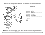
... Wheel Guard 1 4 039029001031 Square Nut (M5 1 5 039029001002 Screw (M5 x 16 mm 1 10 6 039029001042 Disc Flange 1 7 039028001051 Grinding Wheel 1 8 039028001001 Clamp Nut (5/8-11 1 9 039028001052 Wrench 1 10 039028001055 Auxilliary Handle 1 NOT SHOWN: 039028002021 990000434 4-19-13 (Rev:01) Power Cord Label Operator's Manual (039029008004) 8 WARNING: Improper repair of your ANGLE GRINDER or when ordering repair parts. 1 4 5 6 2 3 7 9 PARTS LIST KEY NO. MODEL NUMBER AG403 The model number will be performed by a Ryobi Authorized Service...
... Wheel Guard 1 4 039029001031 Square Nut (M5 1 5 039029001002 Screw (M5 x 16 mm 1 10 6 039029001042 Disc Flange 1 7 039028001051 Grinding Wheel 1 8 039028001001 Clamp Nut (5/8-11 1 9 039028001052 Wrench 1 10 039028001055 Auxilliary Handle 1 NOT SHOWN: 039028002021 990000434 4-19-13 (Rev:01) Power Cord Label Operator's Manual (039029008004) 8 WARNING: Improper repair of your ANGLE GRINDER or when ordering repair parts. 1 4 5 6 2 3 7 9 PARTS LIST KEY NO. MODEL NUMBER AG403 The model number will be performed by a Ryobi Authorized Service...
User Manual 3
Page 2
PART NUMBER DESCRIPTION QTY 1 039029010014 Data Label 1 2 039029001032 Logo Label 1 3 039029001001 Wheel Guard 1 4 039029001031 Square Nut (M5 1 5 039029001002 Screw (M5 x 16 mm 1 10 6 039029001042 Disc Flange 1 7 039028001051 Grinding Wheel 1 8 039028001001 Clamp Nut (5/8-11 1 9 039028001052 Wrench 1 10 039029010013 Auxilliary Handle 1 NOT SHOWN: 990000434 2-13-15 (Rev:01) Operator's Manual (039029010017) 8 WARNING: Improper repair of your ANGLE GRINDER or when ordering repair parts. 1 4 5 6 2 3 7 9 PARTS LIST KEY NO. Any repairs ...
PART NUMBER DESCRIPTION QTY 1 039029010014 Data Label 1 2 039029001032 Logo Label 1 3 039029001001 Wheel Guard 1 4 039029001031 Square Nut (M5 1 5 039029001002 Screw (M5 x 16 mm 1 10 6 039029001042 Disc Flange 1 7 039028001051 Grinding Wheel 1 8 039028001001 Clamp Nut (5/8-11 1 9 039028001052 Wrench 1 10 039029010013 Auxilliary Handle 1 NOT SHOWN: 990000434 2-13-15 (Rev:01) Operator's Manual (039029010017) 8 WARNING: Improper repair of your ANGLE GRINDER or when ordering repair parts. 1 4 5 6 2 3 7 9 PARTS LIST KEY NO. Any repairs ...


