Repair Sheet
Page 3
... the motor housing. Key 25 1 54 080900062522 Switch Key 1 55 089027001026 Washer (M5 1 56 BD46039 Hex Nut (M5, Type I 1 57 089027001028 Capacitor (100uf/125v 1 58 BD46012 Capacitor Support 1 BD46077 Screw (M5 x 12 mm, Pan Hd 1 59 PART NUMBER DESCRIPTION QTY. 089027001029 Bolt (M6 x 12 mm, Hex Hd 3 BD46053 Set Screw (M8 x 12 mm, Hex Hd 2 089027001030 Work Table Support 1 BD46095 Miter Gauge Knob 1 089027001031 Work Table 1 BD46046 Cotter Pin (2 x 10 1 BD46036 Belt Tension Spring...
... the motor housing. Key 25 1 54 080900062522 Switch Key 1 55 089027001026 Washer (M5 1 56 BD46039 Hex Nut (M5, Type I 1 57 089027001028 Capacitor (100uf/125v 1 58 BD46012 Capacitor Support 1 BD46077 Screw (M5 x 12 mm, Pan Hd 1 59 PART NUMBER DESCRIPTION QTY. 089027001029 Bolt (M6 x 12 mm, Hex Hd 3 BD46053 Set Screw (M8 x 12 mm, Hex Hd 2 089027001030 Work Table Support 1 BD46095 Miter Gauge Knob 1 089027001031 Work Table 1 BD46046 Cotter Pin (2 x 10 1 BD46036 Belt Tension Spring...
Repair Sheet
Page 4
RYOBI BELT AND DISC SANDER - Hd 1 089027001041 Belt Guard 1 089027001042 Square Nut (M8 1 BD46076 Drive Pulley 1 BD46043 Roll Pin (5 x 8 2 BD46044 Tension Plate 1 089027001701 Motor Assembly 1 089027001708 Power Cord w/Label (Inc. x 36 in . PARTS LIST KEY NO. 60 61 62 63 64 65 66 67 68 69 70 71 72 73 74 75 76 77 78 79 80 81 82 83 84 PART NUMBER DESCRIPTION QTY. BD46075 Drive Belt 1 BD46015 Idler Pulley 1 089027001018...
RYOBI BELT AND DISC SANDER - Hd 1 089027001041 Belt Guard 1 089027001042 Square Nut (M8 1 BD46076 Drive Pulley 1 BD46043 Roll Pin (5 x 8 2 BD46044 Tension Plate 1 089027001701 Motor Assembly 1 089027001708 Power Cord w/Label (Inc. x 36 in . PARTS LIST KEY NO. 60 61 62 63 64 65 66 67 68 69 70 71 72 73 74 75 76 77 78 79 80 81 82 83 84 PART NUMBER DESCRIPTION QTY. BD46075 Drive Belt 1 BD46015 Idler Pulley 1 089027001018...

User Manual
Page 2
... from state to www. TABLE OF CONTENTS Introduction...2 Warranty...2 General Safety Rules...3-4 Specific Safety Rules...4 Symbols...5 Electrical...6 Features...7 Assembly...8-9 Operation...9-11 Adjustments...11 Maintenance...12 Figure numbers (illustrations)...13-18 Parts Ordering / Service...Back Page INTRODUCTION This tool has many features for...
... from state to www. TABLE OF CONTENTS Introduction...2 Warranty...2 General Safety Rules...3-4 Specific Safety Rules...4 Symbols...5 Electrical...6 Features...7 Assembly...8-9 Operation...9-11 Adjustments...11 Maintenance...12 Figure numbers (illustrations)...13-18 Parts Ordering / Service...Back Page INTRODUCTION This tool has many features for...

User Manual
Page 3
... to this tool. GUARD AGAINST ELECTRICAL SHOCK BY PREVENTING BODY CONTACT WITH GROUNDED SURFACES. Follow instructions for best and safest performance. The use power tools in length. Don't leave tool until it well away from tool before servicing, or when changing attachments, blades, bits, cutters, etc., all instructions listed below, may affect its intended function. If repair or replacement of parts, mounting and any tool. USE RECOMMENDED ACCESSORIES. GENERAL SAFETY RULES...
... to this tool. GUARD AGAINST ELECTRICAL SHOCK BY PREVENTING BODY CONTACT WITH GROUNDED SURFACES. Follow instructions for best and safest performance. The use power tools in length. Don't leave tool until it well away from tool before servicing, or when changing attachments, blades, bits, cutters, etc., all instructions listed below, may affect its intended function. If repair or replacement of parts, mounting and any tool. USE RECOMMENDED ACCESSORIES. GENERAL SAFETY RULES...

User Manual
Page 4
... operation freehand. SPECIFIC SAFETY RULES FIRMLY CLAMP OR BOLT your tool to power supply. ALWAYS REMEMBER that a careless fraction of a second is tight and not making contact with sander or workpiece before disconnecting it will not slip and be replaced only by the manufacturer or by hand. USE EXTRA SUPPORTS (TABLES, SAW HORSES, BLOCKS, ETC.) for safe use this tool, loan them these instructions...
... operation freehand. SPECIFIC SAFETY RULES FIRMLY CLAMP OR BOLT your tool to power supply. ALWAYS REMEMBER that a careless fraction of a second is tight and not making contact with sander or workpiece before disconnecting it will not slip and be replaced only by the manufacturer or by hand. USE EXTRA SUPPORTS (TABLES, SAW HORSES, BLOCKS, ETC.) for safe use this tool, loan them these instructions...

User Manual
Page 5
... and safer. V A Hz min no .../min Volts Amperes Hertz Minutes Alternating Current No Load Speed Per Minute Voltage Current Frequency (cycles per second) Time Type of current Rotational speed, at no load Revolutions, strokes, surface speed, orbits etc., per minute CALIFORNIA PROPOSITION 65 WARNING: This product and some dust created by power sanding, sawing, grinding, drilling, and other reproductive harm. SYMBOL SIGNAL...
... and safer. V A Hz min no .../min Volts Amperes Hertz Minutes Alternating Current No Load Speed Per Minute Voltage Current Frequency (cycles per second) Time Type of current Rotational speed, at no load Revolutions, strokes, surface speed, orbits etc., per minute CALIFORNIA PROPOSITION 65 WARNING: This product and some dust created by power sanding, sawing, grinding, drilling, and other reproductive harm. SYMBOL SIGNAL...

User Manual
Page 6
... proper outlet installed by a precision-built electric motor. NOTE: AWG = American Wire Gauge When working with an electric cord having an outer surface that is approximately 1,900 SFM. Before using a power tool at a considerable distance from the power source, use an extension cord heavy enough to determine the minimum wire size required in serious personal injury. Failure to support two or three tools. Do not operate this tool is heavy...
... proper outlet installed by a precision-built electric motor. NOTE: AWG = American Wire Gauge When working with an electric cord having an outer surface that is approximately 1,900 SFM. Before using a power tool at a considerable distance from the power source, use an extension cord heavy enough to determine the minimum wire size required in serious personal injury. Failure to support two or three tools. Do not operate this tool is heavy...

User Manual
Page 7
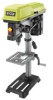
... attempting. SWITCH AND SWITCH KEY Your belt/disc sander has an easy access power switch. English Disc Speed 3,600 r/min. (RPM) Table Size 8-7/8 in . WORK TABLE Equipped with a sturdy work table that indicates the degrees the worktable can be tilted up to 45°. x 6-1/4 in . BEVEL SCALE The worktable comes equipped with all operating features and safety rules. MITER GAUGE The miter gauge aligns the wood for easy belt replacement. WORK SUPPORT (BACKSTOP) Supports the workpiece...
... attempting. SWITCH AND SWITCH KEY Your belt/disc sander has an easy access power switch. English Disc Speed 3,600 r/min. (RPM) Table Size 8-7/8 in . WORK TABLE Equipped with a sturdy work table that indicates the degrees the worktable can be tilted up to 45°. x 6-1/4 in . BEVEL SCALE The worktable comes equipped with all operating features and safety rules. MITER GAUGE The miter gauge aligns the wood for easy belt replacement. WORK SUPPORT (BACKSTOP) Supports the workpiece...
User Manual
Page 8
... running counterclockwise. Parts on a level work surface. After assembling it . n Using the hex key provided, loosen the positioning bolt by retightening the positioning bolt. n Move the sanding belt into place to possible serious personal injury. A Work table 1 B Miter gauge 1 C Sanding disc 1 D Socket head screws 2 E Disc guard 1 F Phillips screw 2 G Work support 1 H Hex key 1 I Washers 2 J Washer 1 K Table lock knob 1 Operator's Manual (not shown 1 UNPACKING This product requires assembly. Carefully lift sander from the sanding disc. Use of this...
... running counterclockwise. Parts on a level work surface. After assembling it . n Using the hex key provided, loosen the positioning bolt by retightening the positioning bolt. n Move the sanding belt into place to possible serious personal injury. A Work table 1 B Miter gauge 1 C Sanding disc 1 D Socket head screws 2 E Disc guard 1 F Phillips screw 2 G Work support 1 H Hex key 1 I Washers 2 J Washer 1 K Table lock knob 1 Operator's Manual (not shown 1 UNPACKING This product requires assembly. Carefully lift sander from the sanding disc. Use of this...
User Manual
Page 9
... a washer over the table lock knob then tighten the table lock knob securely. n Place the work support over the holes in the sanding belt arm. If the belt/disc sander is to be used as a portable tool, it is recommended you secure it permanently to be used in a permanent location, it is recommended you careless. CLAMPING BELT/DISC SANDER TO WORKBENCH See Figure 10, page 15. If the belt/disc sander is to a mounting...
... a washer over the table lock knob then tighten the table lock knob securely. n Place the work support over the holes in the sanding belt arm. If the belt/disc sander is to be used as a portable tool, it is recommended you secure it permanently to be used in a permanent location, it is recommended you careless. CLAMPING BELT/DISC SANDER TO WORKBENCH See Figure 10, page 15. If the belt/disc sander is to a mounting...

User Manual
Page 10
... sander to the edge of control. n Set worktable to a full and complete stop. A miter gauge is recommended for increased accuracy. Use of accidental starting when power returns. The belt/disc sander can sand both vertically and horizontally. n Using the hex key provided, loosen the positioning bolt by retightening the positioning bolt. n Move the sanding belt into the switch, lift the switch button to be tilted from the switch assembly. n Lock the sanding belt by turning...
... sander to the edge of control. n Set worktable to a full and complete stop. A miter gauge is recommended for increased accuracy. Use of accidental starting when power returns. The belt/disc sander can sand both vertically and horizontally. n Using the hex key provided, loosen the positioning bolt by retightening the positioning bolt. n Move the sanding belt into the switch, lift the switch button to be tilted from the switch assembly. n Lock the sanding belt by turning...

User Manual
Page 11
... work table square to remove the material. WARNING: Never attempt to fly up 1/4 turn it OFF. n Hold the workpiece firmly, keeping fingers away from the sanding disc. ADJUSTMENTS WARNING: Before performing any adjustment, make sure the tool is unplugged from the power supply and the switch is in belt/disc sander. n Turn the switch ON and then immediately OFF again, noting belt movement. n Using a combination square, check the angle...
... work table square to remove the material. WARNING: Never attempt to fly up 1/4 turn it OFF. n Hold the workpiece firmly, keeping fingers away from the sanding disc. ADJUSTMENTS WARNING: Before performing any adjustment, make sure the tool is unplugged from the power supply and the switch is in belt/disc sander. n Turn the switch ON and then immediately OFF again, noting belt movement. n Using a combination square, check the angle...
User Manual
Page 12
... operation. n Remove the old drive belt. Tighten securely. GENERAL MAINTENANCE Avoid using solvents when cleaning plastic parts. Therefore, no further lubrication is in the center of give. n Using a phillips head screwdriver, remove the screw in the off ( O ) position. MAINTENANCE WARNING: When servicing, use . WARNING: Always wear eye protection with side shields marked to heed this tool are susceptible to loosen the belt tension. Failure to comply with plastic parts. CHANGING DRIVE BELT...
... operation. n Remove the old drive belt. Tighten securely. GENERAL MAINTENANCE Avoid using solvents when cleaning plastic parts. Therefore, no further lubrication is in the center of give. n Using a phillips head screwdriver, remove the screw in the off ( O ) position. MAINTENANCE WARNING: When servicing, use . WARNING: Always wear eye protection with side shields marked to heed this tool are susceptible to loosen the belt tension. Failure to comply with plastic parts. CHANGING DRIVE BELT...
User Manual 3
Page 3
... Switch Key 1 56 089027001026 Washer (M5 1 57 BD46039 Hex Nut (M5, Type I 1 58 089027001028 Capacitor (100uf/125v 1 BD46012 Capacitor Support 1 59 BD46077 Screw (M5 x 12 mm, Pan Hd 1 60 089027001029 Bolt (M6 x 12 mm, Hex Hd 3 61 PART NUMBER DESCRIPTION QTY BD46053 Set Screw (M8 x 12 mm, Hex Hd 2 089027001054 Work Table Support 1 080027003005 Bevel Gauge Knob 1 089027001710 Work Table 1 BD46046 Cotter Pin (2 x 10 1 BD46036 Belt Tension Spring 1 BD46028 Bushing 2 BD46035 Belt Tension Support...
... Switch Key 1 56 089027001026 Washer (M5 1 57 BD46039 Hex Nut (M5, Type I 1 58 089027001028 Capacitor (100uf/125v 1 BD46012 Capacitor Support 1 59 BD46077 Screw (M5 x 12 mm, Pan Hd 1 60 089027001029 Bolt (M6 x 12 mm, Hex Hd 3 61 PART NUMBER DESCRIPTION QTY BD46053 Set Screw (M8 x 12 mm, Hex Hd 2 089027001054 Work Table Support 1 080027003005 Bevel Gauge Knob 1 089027001710 Work Table 1 BD46046 Cotter Pin (2 x 10 1 BD46036 Belt Tension Spring 1 BD46028 Bushing 2 BD46035 Belt Tension Support...

User Manual 3
Page 4
... ordering repair parts. Key No. 91 1 089027003705 Dust Collection Port 1 BD46034 Roll Pin (5 x 10 1 089027001044 Belt Frame Support 1 BD46024 * Sanding Belt (4 in ., 80 Grit 1 BD46107 Switch Holder 1 089027001045 Screw (M2.9 x 8 mm, Pan Hd 2 BD46004 Washer (D8 2 089027001046 Screw (M8 x 16 mm, Hex Soc. Always mention the model number in all correspondence regarding your tool requires safety testing and should only be found on a label attached to the motor housing. RYOBI BELT...
... ordering repair parts. Key No. 91 1 089027003705 Dust Collection Port 1 BD46034 Roll Pin (5 x 10 1 089027001044 Belt Frame Support 1 BD46024 * Sanding Belt (4 in ., 80 Grit 1 BD46107 Switch Holder 1 089027001045 Screw (M2.9 x 8 mm, Pan Hd 2 BD46004 Washer (D8 2 089027001046 Screw (M8 x 16 mm, Hex Soc. Always mention the model number in all correspondence regarding your tool requires safety testing and should only be found on a label attached to the motor housing. RYOBI BELT...


