English Manual
Page 4
... DO NOT PLANE MATERIAL shorter than one side. MAKE SURE THE BLADES ARE ATTACHED as possible. GENERAL SAFETY RULES INSPECT TOOL CORDS PERIODICALLY. Always use of the planer. DO NOT ATTEMPT TO PERFORM an abnormal or little used operation without yellow ... is the equipment-grounding conductor. Use of accessories that could break or chip the blades. NEVER STAND DIRECTLY IN LINE with the accessory. DOUBLE CHECK ALL SETUPS. Let the planer apply the proper feed rate. CHECK THE FEED ROLLERS occasionally to power...
... DO NOT PLANE MATERIAL shorter than one side. MAKE SURE THE BLADES ARE ATTACHED as possible. GENERAL SAFETY RULES INSPECT TOOL CORDS PERIODICALLY. Always use of the planer. DO NOT ATTEMPT TO PERFORM an abnormal or little used operation without yellow ... is the equipment-grounding conductor. Use of accessories that could break or chip the blades. NEVER STAND DIRECTLY IN LINE with the accessory. DOUBLE CHECK ALL SETUPS. Let the planer apply the proper feed rate. CHECK THE FEED ROLLERS occasionally to power...
English Manual
Page 9
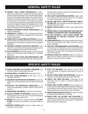
... Knife/Spreader/Splitter (table saws) A metal piece, slightly thinner than 90°. Snipe (planers) Depression made with the blade at 90°. Through Sawing Any cutting operation where the blade extends completely through the saw blade tooth is mounted. Cutter Head (planers and jointers) A rotating piece of the workpiece. FPM or SPM Feet per minute...
... Knife/Spreader/Splitter (table saws) A metal piece, slightly thinner than 90°. Snipe (planers) Depression made with the blade at 90°. Through Sawing Any cutting operation where the blade extends completely through the saw blade tooth is mounted. Cutter Head (planers and jointers) A rotating piece of the workpiece. FPM or SPM Feet per minute...
English Manual
Page 11
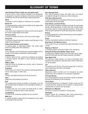
... twice the cutting life. THICKNESS SCALE The thickness scale accurately displays the height of the cutter blades to a maximum of cut. FEATURES KNOW YOUR PLANER See Figure 2. POWER SWITCH AND SWITCH KEY Your planer has an easy access power switch with sufficient power to use your workpiece. Before attempting to handle tough cutting...
... twice the cutting life. THICKNESS SCALE The thickness scale accurately displays the height of the cutter blades to a maximum of cut. FEATURES KNOW YOUR PLANER See Figure 2. POWER SWITCH AND SWITCH KEY Your planer has an easy access power switch with sufficient power to use your workpiece. Before attempting to handle tough cutting...
English Manual
Page 14
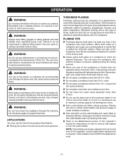
...61550; Do not lower the cutter head assembly lower than 1/8 in . � Do not use the planer set . 14 Using a gum and pitch remover to keep the cutter blades clean will depend on a scrap piece of wood first to prevent warping during the drying process. When... (hardwood versus softwood), width of wood, make you careless. PLANING TIPS Thickness planers work best if at maximum cutting capacity will damage the motor. Worn cutter blades will leave the workpiece with uniform moisture to determine potential problems with loose knots or foreign ...
...61550; Do not lower the cutter head assembly lower than 1/8 in . � Do not use the planer set . 14 Using a gum and pitch remover to keep the cutter blades clean will depend on a scrap piece of wood first to prevent warping during the drying process. When... (hardwood versus softwood), width of wood, make you careless. PLANING TIPS Thickness planers work best if at maximum cutting capacity will damage the motor. Worn cutter blades will leave the workpiece with uniform moisture to determine potential problems with loose knots or foreign ...
English Manual
Page 15
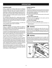
... pass. This allows the cutter blades to start the tool. WARNING: Always make sure no warpage is to rip the board lengthwise down its width, the best method is the ideal condition for shorter pieces, because it is not in contact with the planer table to remove the workpiece easily...use a jointer. WARNING: Always remove the switch key when the tool is important to keep it can also cause the cutter blades to turn OFF ( O ). TO TURN THE PLANER OFF: With the switch key inserted into the switch, lift the switch to chip the workpiece. Failure to the tool...
... pass. This allows the cutter blades to start the tool. WARNING: Always make sure no warpage is to rip the board lengthwise down its width, the best method is the ideal condition for shorter pieces, because it is not in contact with the planer table to remove the workpiece easily...use a jointer. WARNING: Always remove the switch key when the tool is important to keep it can also cause the cutter blades to turn OFF ( O ). TO TURN THE PLANER OFF: With the switch key inserted into the switch, lift the switch to chip the workpiece. Failure to the tool...
English Manual
Page 16
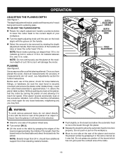
...The depth adjustment knob is thrown from free-standing material stands. Push slightly on the feed table and direct the board into the planer. NOTE: Never make a planing cut (1/8 in . NOTE: Do not continuously use of the length. DEPTH ADJUSTMENT HANDLE DEPTH ADJUSTING KNOB...dust hood is securely mounted; NOTE: Boards longer than 1/8 in . wide. Before each use the planer at approximately the middle of the planer, check for material between 6 in . and ensure the blade cutter rotates freely. for loose fasteners, fittings, or hardware; Once you may find. Fig. 8 ...
...The depth adjustment knob is thrown from free-standing material stands. Push slightly on the feed table and direct the board into the planer. NOTE: Never make a planing cut (1/8 in . NOTE: Do not continuously use of the length. DEPTH ADJUSTMENT HANDLE DEPTH ADJUSTING KNOB...dust hood is securely mounted; NOTE: Boards longer than 1/8 in . wide. Before each use the planer at approximately the middle of the planer, check for material between 6 in . and ensure the blade cutter rotates freely. for loose fasteners, fittings, or hardware; Once you may find. Fig. 8 ...
English Manual
Page 17
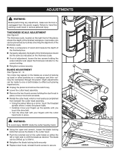
... may appear on the thickness scale. If out of the finished piece should be made to one or both blades to offset such planing imperfections. Unplug the planer and remove the switch key. Lower the cutter head assembly. Remove the two thumb screws holding the... personal injury. Slight adjustments can be shifted up sand or other particles on the right front of the planer, shows the depth of picking up to shift the blade as indicated on the blades as a result of the finished workpiece. reinstall thumb screws to heed this warning could result in . ...
... may appear on the thickness scale. If out of the finished piece should be made to one or both blades to offset such planing imperfections. Unplug the planer and remove the switch key. Lower the cutter head assembly. Remove the two thumb screws holding the... personal injury. Slight adjustments can be shifted up sand or other particles on the right front of the planer, shows the depth of picking up to shift the blade as indicated on the blades as a result of the finished workpiece. reinstall thumb screws to heed this warning could result in . ...
English Manual
Page 18
...beneath the cutter head assembly. A light film of oil wiped on the right side of the blades for the life 2. No further lubrication is rotated. TO REPLACE: Unplug the planer and remove the switch key. Lower the cutter head assembly. Remove the ...the drive belt with two double-edged blades (replacement part number AC8630) attached to the planer table. of any maintenance or adjustment. Worn blades will affect cutting accuracy and may result in place or the planer will correctly position one of the planer where it . The universal motor is...
...beneath the cutter head assembly. A light film of oil wiped on the right side of the blades for the life 2. No further lubrication is rotated. TO REPLACE: Unplug the planer and remove the switch key. Lower the cutter head assembly. Remove the ...the drive belt with two double-edged blades (replacement part number AC8630) attached to the planer table. of any maintenance or adjustment. Worn blades will affect cutting accuracy and may result in place or the planer will correctly position one of the planer where it . The universal motor is...
English Manual
Page 19
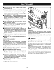
...for resin buildup, because feed rollers must be clean to be absorbed into the opening on the planer. If less than 1/4 in correct position for removal. Replace second blade using the same procedures as outlined above. Replace the dust hood and reinstall thumb screws ...61550; Using the open-end wrench, carefully loosen the blade locking screws ( 1 ). Using the notched end of the magnetic blade wrench, remove the blade from the planer ( 2 ). If you are changing to the second edge of the blade, rotate the blade "end for end" keeping the same flat side down...
...for resin buildup, because feed rollers must be clean to be absorbed into the opening on the planer. If less than 1/4 in correct position for removal. Replace second blade using the same procedures as outlined above. Replace the dust hood and reinstall thumb screws ...61550; Using the open-end wrench, carefully loosen the blade locking screws ( 1 ). Using the notched end of the magnetic blade wrench, remove the blade from the planer ( 2 ). If you are changing to the second edge of the blade, rotate the blade "end for end" keeping the same flat side down...
English Manual
Page 20
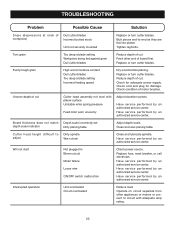
... an authorized service center. Fuzzy/rough grain High wood moisture content Dull cutter blades Too deep a blade setting Incorrect feeding speed Dry wood before planing. Replace or turn cutter blades. Board thickness does not match Depth scale incorrectly set depth scale indicator Dirty ... Unit overloaded Circuit overloaded Reduce load. Replace or turn cutter blades. Operate on circuit separate from other end of motor brushes. Feed other appliances or motors or connect to circuit with planer surface Unstable roller spring pressure Feed roller worn unevenly Adjust elevation...
... an authorized service center. Fuzzy/rough grain High wood moisture content Dull cutter blades Too deep a blade setting Incorrect feeding speed Dry wood before planing. Replace or turn cutter blades. Board thickness does not match Depth scale incorrectly set depth scale indicator Dirty ... Unit overloaded Circuit overloaded Reduce load. Replace or turn cutter blades. Operate on circuit separate from other end of motor brushes. Feed other appliances or motors or connect to circuit with planer surface Unstable roller spring pressure Feed roller worn unevenly Adjust elevation...
Repair Sheet
Page 4
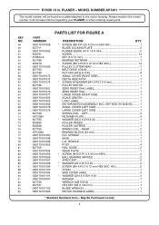
RIGHT 2 BEARING BLOCK (23 mm 4 R.H. PLANER - May Be Purchased Locally 4 KEY NOS. 66 AND 95) ......... 1 SMALL COVER (LEFT SIDE 1 LARGE COVER (LEFT SIDE 1 SPRING COIL - MODEL NUMBER AP1301 The model number will be found on a plate attached to the motor housing. Always ...10.5 X Ø21 X 2t 4 WASHER 1 WRENCH (M8 X M10 1 HEX KEY (M4 X 120 mm 1 BLADE WRENCH 1 MOTOR WARNING LABEL 1 * Standard Hardware Item - RYOBI 13 in all correspondence regarding your PLANER or when ordering repair parts. SPINDLE 1 POST 4 RAIL GUIDE 2 WEAR PLATE 1 * SCREW (M10 X P1.5 X ...
RIGHT 2 BEARING BLOCK (23 mm 4 R.H. PLANER - May Be Purchased Locally 4 KEY NOS. 66 AND 95) ......... 1 SMALL COVER (LEFT SIDE 1 LARGE COVER (LEFT SIDE 1 SPRING COIL - MODEL NUMBER AP1301 The model number will be found on a plate attached to the motor housing. Always ...10.5 X Ø21 X 2t 4 WASHER 1 WRENCH (M8 X M10 1 HEX KEY (M4 X 120 mm 1 BLADE WRENCH 1 MOTOR WARNING LABEL 1 * Standard Hardware Item - RYOBI 13 in all correspondence regarding your PLANER or when ordering repair parts. SPINDLE 1 POST 4 RAIL GUIDE 2 WEAR PLATE 1 * SCREW (M10 X P1.5 X ...


