
English Manual
Page 1
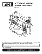
Thank you years of rugged, trouble-free performance. PORTABLE PLANER AP1301 Your portable planer has been engineered and manufactured to our high standard for your purchase. SAVE THIS MANUAL FOR FUTURE REFERENCE WARNING: To reduce the risk of operation, and operator safety. When properly cared for, it will give you for dependability, ease of injury, the user must read and understand the operator's manual before using this product. OPERATOR'S MANUAL 13 in.
Thank you years of rugged, trouble-free performance. PORTABLE PLANER AP1301 Your portable planer has been engineered and manufactured to our high standard for your purchase. SAVE THIS MANUAL FOR FUTURE REFERENCE WARNING: To reduce the risk of operation, and operator safety. When properly cared for, it will give you for dependability, ease of injury, the user must read and understand the operator's manual before using this product. OPERATOR'S MANUAL 13 in.
English Manual
Page 4
... screws are doing and use of sturdy and adequate jigs, fixtures, stops, and the like. NEVER plane more than one workpiece on the planer table at a time. If damaged, have 3-prong grounding plugs and 3-pole receptacles that is properly grounded. USE ONLY CORRECT ELECTRICAL DEVICES: ... the tool is green with either the infeed or outfeed sides. Use caution in . Instructions for tightness after about 50 hours of the planer. DO NOT ATTEMPT TO PERFORM an abnormal or little used operation without yellow stripes is tight and not making contact with the ...
... screws are doing and use of sturdy and adequate jigs, fixtures, stops, and the like. NEVER plane more than one workpiece on the planer table at a time. If damaged, have 3-prong grounding plugs and 3-pole receptacles that is properly grounded. USE ONLY CORRECT ELECTRICAL DEVICES: ... the tool is green with either the infeed or outfeed sides. Use caution in . Instructions for tightness after about 50 hours of the planer. DO NOT ATTEMPT TO PERFORM an abnormal or little used operation without yellow stripes is tight and not making contact with the ...
English Manual
Page 5
... operation. ALWAYS STAY ALERT! If you do this tool, loan them frequently and use of work using your planer. ALWAYS TURN OFF TOOL before using the planer. REPLACEMENT PARTS. To reduce your exposure to these exposures varies, depending on how often you loan someone this...center to avoid risk. SAVE THESE INSTRUCTIONS. Your risk from these chemicals, work in any way, or should be made at your planer) to perform properly, shut off the power switch, remove the plug from frequent use to reach full speed before disconnecting it, to avoid ...
... operation. ALWAYS STAY ALERT! If you do this tool, loan them frequently and use of work using your planer. ALWAYS TURN OFF TOOL before using the planer. REPLACEMENT PARTS. To reduce your exposure to these exposures varies, depending on how often you loan someone this...center to avoid risk. SAVE THESE INSTRUCTIONS. Your risk from these chemicals, work in any way, or should be made at your planer) to perform properly, shut off the power switch, remove the plug from frequent use to reach full speed before disconnecting it, to avoid ...
English Manual
Page 9
Bevel Cut A cutting operation made with the workpiece at any ripping operation. Cutter Head (planers and jointers) A rotating piece of the workpiece. Dado Cut A non-through the saw blade during cutting operations. Kickback A hazard that can occur when the blade ... by guiding it applies to the workpiece, that serves as a guide for narrow ripping operations. Revolutions Per Minute (r/min.) The number of the blade. Snipe (planers) Depression made with the blade at any angle to the blade other than 90° to the table surface. Cross Cut A cutting or shaping operation...
Bevel Cut A cutting operation made with the workpiece at any ripping operation. Cutter Head (planers and jointers) A rotating piece of the workpiece. Dado Cut A non-through the saw blade during cutting operations. Kickback A hazard that can occur when the blade ... by guiding it applies to the workpiece, that serves as a guide for narrow ripping operations. Revolutions Per Minute (r/min.) The number of the blade. Snipe (planers) Depression made with the blade at any angle to the blade other than 90° to the table surface. Cross Cut A cutting or shaping operation...
English Manual
Page 11
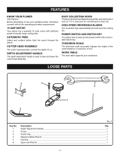
... Handle ...1 Screw ...1 Switch Key...1 Magnetic Blade Wrench ...1 Hex Key ...1 Open-end Wrench ...1 11 FEATURES KNOW YOUR PLANER See Figure 2. AUTOMATIC FEED Infeed and outfeed rollers feed the wood through the planer. DUST COLLECTION HOOD The dust collection hood features a quick flip-up dumping door and a 2-1/4 in . POWER SWITCH... AND SWITCH KEY Your planer has an easy access power switch with sufficient power to raise and lower the cutter head assembly. THICKNESS SCALE The thickness scale...
... Handle ...1 Screw ...1 Switch Key...1 Magnetic Blade Wrench ...1 Hex Key ...1 Open-end Wrench ...1 11 FEATURES KNOW YOUR PLANER See Figure 2. AUTOMATIC FEED Infeed and outfeed rollers feed the wood through the planer. DUST COLLECTION HOOD The dust collection hood features a quick flip-up dumping door and a 2-1/4 in . POWER SWITCH... AND SWITCH KEY Your planer has an easy access power switch with sufficient power to raise and lower the cutter head assembly. THICKNESS SCALE The thickness scale...
English Manual
Page 13
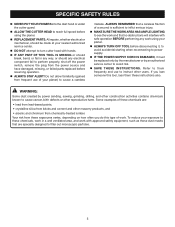
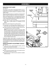
... or support surface before beginning planing operation. minimum thickness is recommended. Mark holes on mounting surface, aligning holes in the planer base with lock washers and hex nuts (not included). If machine bolts are used, make sure they are long enough to go through...to go through holes in the mounting surface. Insert four bolts (not included) and tighten securely with holes drilled in planer base and material the planer is to be easily clamped to a workbench or other stable surface. MOUNTING BOARD WORKBENCH Fig. 4 DEPTH ADJUSTMENT HANDLE WITH SCREW Fig...
... or support surface before beginning planing operation. minimum thickness is recommended. Mark holes on mounting surface, aligning holes in the planer base with lock washers and hex nuts (not included). If machine bolts are used, make sure they are long enough to go through...to go through holes in the mounting surface. Insert four bolts (not included) and tighten securely with holes drilled in planer base and material the planer is to be easily clamped to a workbench or other stable surface. MOUNTING BOARD WORKBENCH Fig. 4 DEPTH ADJUSTMENT HANDLE WITH SCREW Fig...
English Manual
Page 14
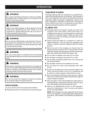
... of attachments or accessories not recommended can result in . � Do not use of a workpiece are rough, use a surface planer or jointer first to the opposite, unused edge before replacement is sufficient to a desired thickness while creating a smooth, level surface. Remember,...Do not lower the cutter head assembly lower than 14 in .). The use this will depend on materials not recommended may damage the planer and may cause serious personal injury. Planing with the workpiece. APPLICATIONS You may produce ridges or rough workpiece surfaces. Gum...
... of attachments or accessories not recommended can result in . � Do not use of a workpiece are rough, use a surface planer or jointer first to the opposite, unused edge before replacement is sufficient to a desired thickness while creating a smooth, level surface. Remember,...Do not lower the cutter head assembly lower than 14 in .). The use this will depend on materials not recommended may damage the planer and may cause serious personal injury. Planing with the workpiece. APPLICATIONS You may produce ridges or rough workpiece surfaces. Gum...
English Manual
Page 15
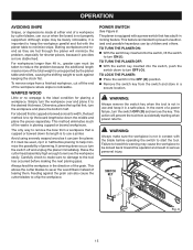
...workpiece easily. This action will minimize the problem, especially for planing a workpiece. Butting workpieces end-toend as it is equipped with the planer table to minimize snipe. This method eliminates much of the waste in ., greater care must be kicked back toward the operator and result... workpiece parallel and flat with a power switch that is intended to remove the bow from the switch and store in locking feature. TO LOCK THE PLANER: Place the switch in the OFF ( O ) position. Remove the switch key from a workpiece that has a built-in a secure location...
...workpiece easily. This action will minimize the problem, especially for planing a workpiece. Butting workpieces end-toend as it is equipped with the planer table to minimize snipe. This method eliminates much of the waste in ., greater care must be kicked back toward the operator and result... workpiece parallel and flat with a power switch that is intended to remove the bow from the switch and store in locking feature. TO LOCK THE PLANER: Place the switch in the OFF ( O ) position. Remove the switch key from a workpiece that has a built-in a secure location...
English Manual
Page 16
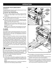
...workpiece. Move to the table by rotating the depth adjustment handle. and ensure the blade cutter rotates freely. Each full revolution of the planer infeed area. Turn switch ON ( l ). Lift the work to one side of the handle will damage the motor.... the depth adjustment handle counterclockwise to lower the cutter head to approximately 1 in . Without putting any you have additional support from the planer, it was fed. should have planed the wood, check all measurements for any loose hardware, retightening any load on the feed table and...
...workpiece. Move to the table by rotating the depth adjustment handle. and ensure the blade cutter rotates freely. Each full revolution of the planer infeed area. Turn switch ON ( l ). Lift the work to one side of the handle will damage the motor.... the depth adjustment handle counterclockwise to lower the cutter head to approximately 1 in . Without putting any you have additional support from the planer, it was fed. should have planed the wood, check all measurements for any loose hardware, retightening any load on the feed table and...
English Manual
Page 17
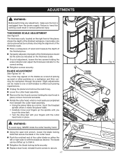
.... Rotate the cutter head, which is unplugged from beneath the cutter head assembly. • Using the planer table as a mirror, touch the threaded spindle where it meets the planer table. • Carefully move your fingers up the spindle until you touch the drive belt. • Turn the... ADJUSTMENT See Figures 10 - 11. Slight adjustments can be made to one or both blades to offset such planing imperfections. Unplug the planer and remove the switch key. Lower the cutter head assembly. Remove the two thumb screws holding the scale indicator and adjust the...
.... Rotate the cutter head, which is unplugged from beneath the cutter head assembly. • Using the planer table as a mirror, touch the threaded spindle where it meets the planer table. • Carefully move your fingers up the spindle until you touch the drive belt. • Turn the... ADJUSTMENT See Figures 10 - 11. Slight adjustments can be made to one or both blades to offset such planing imperfections. Unplug the planer and remove the switch key. Lower the cutter head assembly. Remove the two thumb screws holding the scale indicator and adjust the...
English Manual
Page 18
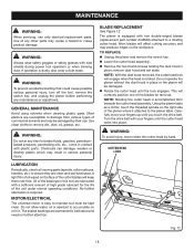
...WARNING: To prevent accidental starting that could cause possible serious personal injury, turn off the tool, remove the switch key, and unplug the planer before performing any time let brake fluids, gasoline, petroleumbased products, penetrating oils, etc., come in place; GENERAL MAINTENANCE Avoid using solvents when ...safety glasses with your fingers up until the lock engages. WARNING: Do not at any maintenance or adjustment. Do not operate the planer without the dust hood in this tool are susceptible to accumulate on the right side of oil wiped on the workpiece. No ...
...WARNING: To prevent accidental starting that could cause possible serious personal injury, turn off the tool, remove the switch key, and unplug the planer before performing any time let brake fluids, gasoline, petroleumbased products, penetrating oils, etc., come in place; GENERAL MAINTENANCE Avoid using solvents when ...safety glasses with your fingers up until the lock engages. WARNING: Do not at any maintenance or adjustment. Do not operate the planer without the dust hood in this tool are susceptible to accumulate on the right side of oil wiped on the workpiece. No ...
English Manual
Page 19
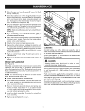
...open-end wrench, carefully loosen the blade locking screws ( 1 ). Using the notched end of the magnetic blade wrench, remove the blade from the planer ( 2 ). If you are changing to the second edge of the blade and pulling straight out. Moving parts should be cleaned regularly with penetrating ...by hooking the notch over the end of the blade, rotate the blade "end for easier access when removing the rear brush cap. Unplug planer and remove the switch key. Using a flat-head screwdriver, unscrew the brush cap. NOTE: The dust hood may be cleaned of gum ...
...open-end wrench, carefully loosen the blade locking screws ( 1 ). Using the notched end of the magnetic blade wrench, remove the blade from the planer ( 2 ). If you are changing to the second edge of the blade and pulling straight out. Moving parts should be cleaned regularly with penetrating ...by hooking the notch over the end of the blade, rotate the blade "end for easier access when removing the rear brush cap. Unplug planer and remove the switch key. Using a flat-head screwdriver, unscrew the brush cap. NOTE: The dust hood may be cleaned of gum ...
English Manual
Page 20
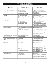
Feed other appliances or motors or connect to circuit with planer surface Unstable roller spring pressure Feed roller worn unevenly Adjust elevation screws. Replace or turn cutter blades. Check condition of board first. Board thickness does ... overloaded Circuit overloaded Reduce load. Replace or turn cutter blades. Uneven depth of cut. Cutter head height difficult to -end as they are fed into planer. Have service performed by an authorized service center. Operate on circuit separate from other end of motor brushes. Check for damage. Tighten lag bolts. Reduce...
Feed other appliances or motors or connect to circuit with planer surface Unstable roller spring pressure Feed roller worn unevenly Adjust elevation screws. Replace or turn cutter blades. Check condition of board first. Board thickness does ... overloaded Circuit overloaded Reduce load. Replace or turn cutter blades. Uneven depth of cut. Cutter head height difficult to -end as they are fed into planer. Have service performed by an authorized service center. Operate on circuit separate from other end of motor brushes. Check for damage. Tighten lag bolts. Reduce...
English Manual
Page 22
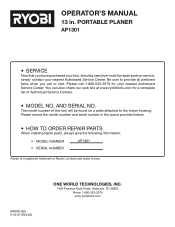
... provided below. • HOW TO ORDER REPAIR PARTS When ordering repair parts, always give the following information: • MODEL NUMBER AP1301 • SERIAL NUMBER Ryobi® is a registered trademark of this tool will be found on a plate attached to provide all pertinent facts when you have ... call or visit. The model number of Ryobi® Limited used under license. 983000-828 9-10-07 (REV:03) ONE WORLD TECHNOLOGIES, INC. 1428 Pearman Dairy Road, Anderson, SC 29625 Phone 1-800-525-2579 www.ryobitools.com 22 PORTABLE PLANER AP1301 • SERVICE Now that you call 1-800...
... provided below. • HOW TO ORDER REPAIR PARTS When ordering repair parts, always give the following information: • MODEL NUMBER AP1301 • SERIAL NUMBER Ryobi® is a registered trademark of this tool will be found on a plate attached to provide all pertinent facts when you have ... call or visit. The model number of Ryobi® Limited used under license. 983000-828 9-10-07 (REV:03) ONE WORLD TECHNOLOGIES, INC. 1428 Pearman Dairy Road, Anderson, SC 29625 Phone 1-800-525-2579 www.ryobitools.com 22 PORTABLE PLANER AP1301 • SERVICE Now that you call 1-800...
Repair Sheet
Page 3
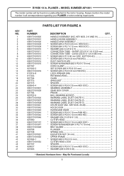
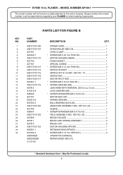
... 12 mm HEX SOC 1 * WASHER (Ø8 X Ø18 X 2t 1 * Standard Hardware Item - May Be Purchased Locally 3 HANDLE ASSEMBLY (INC. MODEL NUMBER AP1301 The model number will be found on a plate attached to the motor housing. KEY NOS. 2-6 AND 91 1 HANDLE KNOB ASSEMBLY 1 HANDLE ARM ASSEMBLY 1 * SCREW (M5... 1 BALL BEARING (6203ZZ 2 WARNING LABEL (DUST CHUTE-1 1 WARNING LABEL (DUST CHUTE-2 1 WARNING LABEL (DUST CHUTE-3 1 CHUTE DUST (INC. RYOBI 13 in all correspondence regarding your PLANER or when ordering repair parts. SHORT (OD.20 X 1.0t X 225 mm 2 CONNECTION TUBE...
... 12 mm HEX SOC 1 * WASHER (Ø8 X Ø18 X 2t 1 * Standard Hardware Item - May Be Purchased Locally 3 HANDLE ASSEMBLY (INC. MODEL NUMBER AP1301 The model number will be found on a plate attached to the motor housing. KEY NOS. 2-6 AND 91 1 HANDLE KNOB ASSEMBLY 1 HANDLE ARM ASSEMBLY 1 * SCREW (M5... 1 BALL BEARING (6203ZZ 2 WARNING LABEL (DUST CHUTE-1 1 WARNING LABEL (DUST CHUTE-2 1 WARNING LABEL (DUST CHUTE-3 1 CHUTE DUST (INC. RYOBI 13 in all correspondence regarding your PLANER or when ordering repair parts. SHORT (OD.20 X 1.0t X 225 mm 2 CONNECTION TUBE...
Repair Sheet
Page 4
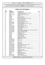
...SMALL COVER (LEFT SIDE 1 LARGE COVER (LEFT SIDE 1 SPRING COIL - SPINDLE 1 BASE 1 L.H. RIGHT 2 BEARING BLOCK (23 mm 4 R.H. RYOBI 13 in all correspondence regarding your PLANER or when ordering repair parts. LEFT 2 RETAINER PLATE 4 * WASHER (Ø5.5 X Ø19 X 2t 1 ROLLER INFEED 1 ROLLER OUTFEED 1 ...SPRING COIL - MODEL NUMBER AP1301 The model number will be found on a plate attached to the motor ...
...SMALL COVER (LEFT SIDE 1 LARGE COVER (LEFT SIDE 1 SPRING COIL - SPINDLE 1 BASE 1 L.H. RIGHT 2 BEARING BLOCK (23 mm 4 R.H. RYOBI 13 in all correspondence regarding your PLANER or when ordering repair parts. LEFT 2 RETAINER PLATE 4 * WASHER (Ø5.5 X Ø19 X 2t 1 ROLLER INFEED 1 ROLLER OUTFEED 1 ...SPRING COIL - MODEL NUMBER AP1301 The model number will be found on a plate attached to the motor ...
Repair Sheet
Page 6
...in . KEY NO. 20 1 SLEEVE 1 * SCREW W/WASHER (M4.8 X 75 mm 2 FIELD ASSEMBLY (INC. May Be Purchased Locally 6 RYOBI 13 in all correspondence regarding your PLANER or when ordering repair parts. KEY NO. 22 1 BRUSH HOLDER 2 BRUSH AND SPRING ASSEMBLY 2 BRUSH CAP 2 MOTOR HOUSING (FRONT 1 RETAINING RING... (RTW32 1 * SCREW (M5 X 12 mm HEX SOC 2 OPERATOR'S MANUAL REPAIR SHEET (REV:01) * Standard Hardware Item - MODEL NUMBER AP1301 ...
...in . KEY NO. 20 1 SLEEVE 1 * SCREW W/WASHER (M4.8 X 75 mm 2 FIELD ASSEMBLY (INC. May Be Purchased Locally 6 RYOBI 13 in all correspondence regarding your PLANER or when ordering repair parts. KEY NO. 22 1 BRUSH HOLDER 2 BRUSH AND SPRING ASSEMBLY 2 BRUSH CAP 2 MOTOR HOUSING (FRONT 1 RETAINING RING... (RTW32 1 * SCREW (M5 X 12 mm HEX SOC 2 OPERATOR'S MANUAL REPAIR SHEET (REV:01) * Standard Hardware Item - MODEL NUMBER AP1301 ...
Repair Sheet
Page 7
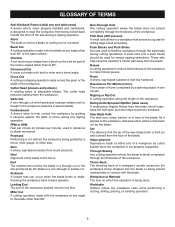
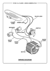
PLANER - MODEL NUMBER AP1301 POWER GREEN LEAD CORD BRUSHES WHITE LEAD WHITE LEAD WHITE LEAD BLACK LEAD SWITCH WHITE LEAD MOTOR WIRING DIAGRAM 7 RYOBI 13 in.
PLANER - MODEL NUMBER AP1301 POWER GREEN LEAD CORD BRUSHES WHITE LEAD WHITE LEAD WHITE LEAD BLACK LEAD SWITCH WHITE LEAD MOTOR WIRING DIAGRAM 7 RYOBI 13 in.


