English Manual
Page 1
When properly cared for, it will give you for dependability, ease of operation, and operator safety. OPERATOR'S MANUAL 13 in. Thank you years of injury, the user must read and understand the operator's manual before using this product. SAVE THIS MANUAL FOR FUTURE REFERENCE WARNING: To reduce the risk of rugged, trouble-free performance. PORTABLE PLANER AP1301 Your portable planer has been engineered and manufactured to our high standard for your purchase.
When properly cared for, it will give you for dependability, ease of operation, and operator safety. OPERATOR'S MANUAL 13 in. Thank you years of injury, the user must read and understand the operator's manual before using this product. SAVE THIS MANUAL FOR FUTURE REFERENCE WARNING: To reduce the risk of rugged, trouble-free performance. PORTABLE PLANER AP1301 Your portable planer has been engineered and manufactured to our high standard for your purchase.
English Manual
Page 13
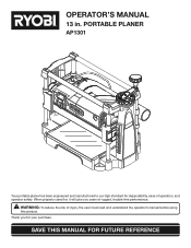
...workbench or support surface before beginning planing operation. MOUNTING BOARD WORKBENCH Fig. 4 DEPTH ADJUSTMENT HANDLE WITH SCREW Fig. 5 13 ASSEMBLY MOUNTING THE PLANER See Figure 4. If the planer is to . If machine bolts are long enough to go through holes in the shaft. Using the hex...good grade plywood or chipboard with lock washers and hex nuts (not included). minimum thickness is recommended. Mark holes on surface where planer is mounted should be used , make sure they are used in a permanent location, it to a workbench or to go through the ...
...workbench or support surface before beginning planing operation. MOUNTING BOARD WORKBENCH Fig. 4 DEPTH ADJUSTMENT HANDLE WITH SCREW Fig. 5 13 ASSEMBLY MOUNTING THE PLANER See Figure 4. If the planer is to . If machine bolts are long enough to go through holes in the shaft. Using the hex...good grade plywood or chipboard with lock washers and hex nuts (not included). minimum thickness is recommended. Mark holes on surface where planer is mounted should be used , make sure they are used in a permanent location, it to a workbench or to go through the ...
English Manual
Page 14
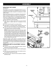
... desired thickness. WARNING: Always wear safety goggles or safety glasses with loose knots or foreign objects. Let the planer apply the proper feed rate. The thickness of each cut (13 in.). thick. Do not plane a workpiece less than 3/16 in. Continuous use at full width...careless. The use of attachments or accessories not recommended can dull, chip, or break, causing possible serious personal injury. PLANING TIPS Thickness planers work best if at least one side of the workpiece has a flat surface. Remember, light cuts create a finer finish than heavier cuts. ...
... desired thickness. WARNING: Always wear safety goggles or safety glasses with loose knots or foreign objects. Let the planer apply the proper feed rate. The thickness of each cut (13 in.). thick. Do not plane a workpiece less than 3/16 in. Continuous use at full width...careless. The use of attachments or accessories not recommended can dull, chip, or break, causing possible serious personal injury. PLANING TIPS Thickness planers work best if at least one side of the workpiece has a flat surface. Remember, light cuts create a finer finish than heavier cuts. ...
English Manual
Page 16
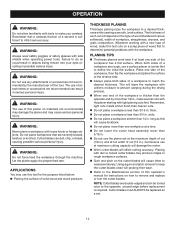
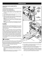
...raise or lower the cutter head 1/16 in a planing pass. Fig. 8 Stand to one side at approximately the middle of the planer and receive the planed lumber by rotating the depth adjustment handle. for accuracy. Once you may find. Lower the cutter head assembly to function properly... dust hood is thrown from free-standing material stands. Push slightly on the feed table and direct the board into the planer. and 13 in . If the planer sounds excessively loud or has excessive vibration, turn off the machine immediately and check again for further instructions.
...raise or lower the cutter head 1/16 in a planing pass. Fig. 8 Stand to one side at approximately the middle of the planer and receive the planed lumber by rotating the depth adjustment handle. for accuracy. Once you may find. Lower the cutter head assembly to function properly... dust hood is thrown from free-standing material stands. Push slightly on the feed table and direct the board into the planer. and 13 in . If the planer sounds excessively loud or has excessive vibration, turn off the machine immediately and check again for further instructions.
English Manual
Page 19
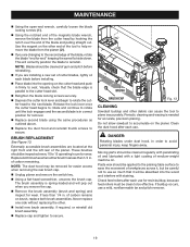
...when removing the rear brush cap. Unplug planer and remove the switch key. Using a flat-head screwdriver, unscrew the brush cap. BRUSH REPLACEMENT See Figure 13. of carbon remaining. of carbon remains on the planer. Never replace one side without replacing the other debris... can cause the tool to secure. BRUSH BRUSH CAP Fig. 13 CLEANING Sawdust buildup and other . Install new...
...when removing the rear brush cap. Unplug planer and remove the switch key. Using a flat-head screwdriver, unscrew the brush cap. BRUSH REPLACEMENT See Figure 13. of carbon remaining. of carbon remains on the planer. Never replace one side without replacing the other debris... can cause the tool to secure. BRUSH BRUSH CAP Fig. 13 CLEANING Sawdust buildup and other . Install new...
English Manual
Page 22
... tool, should a need ever exist for repair parts or service, simply contact your nearest Authorized Service Center. PORTABLE PLANER AP1301 • SERVICE Now that you call 1-800-525-2579 for a complete list of Authorized Service Centers. • MODEL NO. OPERATOR'S... MANUAL 13 in the space provided below. • HOW TO ORDER REPAIR PARTS When ordering repair parts, always give the following information: • MODEL NUMBER AP1301 • SERIAL NUMBER Ryobi® is a registered trademark of Ryobi® Limited used under license. 983000-828...
... tool, should a need ever exist for repair parts or service, simply contact your nearest Authorized Service Center. PORTABLE PLANER AP1301 • SERVICE Now that you call 1-800-525-2579 for a complete list of Authorized Service Centers. • MODEL NO. OPERATOR'S... MANUAL 13 in the space provided below. • HOW TO ORDER REPAIR PARTS When ordering repair parts, always give the following information: • MODEL NUMBER AP1301 • SERIAL NUMBER Ryobi® is a registered trademark of Ryobi® Limited used under license. 983000-828...
Repair Sheet
Page 3
... 1 CONNECTION TUBE - Always mention the model number in . LONG (OD.20 X 1.0t X 485 mm 2 * SCREW (M6 X P1 X 60 mm SOC. KEY NO. 1 2 3 4 5 6 7 8 9 10 11 12 13 14 15 16 17 18 19 20 21 22 23 24 25 26 27 28 29 30 31 32 33 34 35 36 37 38....8 X 12 mm HEX SOC 1 * WASHER (Ø8 X Ø18 X 2t 1 * Standard Hardware Item - MODEL NUMBER AP1301 The model number will be found on a plate attached to the motor housing. May Be Purchased Locally 3 RYOBI 13 in all correspondence regarding your PLANER or when ordering repair parts. SHORT (OD.20 X 1.0t X 225 mm 2 CONNECTION TUBE - BUTTON...
... 1 CONNECTION TUBE - Always mention the model number in . LONG (OD.20 X 1.0t X 485 mm 2 * SCREW (M6 X P1 X 60 mm SOC. KEY NO. 1 2 3 4 5 6 7 8 9 10 11 12 13 14 15 16 17 18 19 20 21 22 23 24 25 26 27 28 29 30 31 32 33 34 35 36 37 38....8 X 12 mm HEX SOC 1 * WASHER (Ø8 X Ø18 X 2t 1 * Standard Hardware Item - MODEL NUMBER AP1301 The model number will be found on a plate attached to the motor housing. May Be Purchased Locally 3 RYOBI 13 in all correspondence regarding your PLANER or when ordering repair parts. SHORT (OD.20 X 1.0t X 225 mm 2 CONNECTION TUBE - BUTTON...
Repair Sheet
Page 4
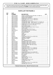
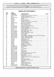
PLANER - Always mention the model number in . LEFT 2 RETAINER PLATE 4 * WASHER (Ø5.5 X Ø... 089170101906 PARTS LIST FOR FIGURE A DESCRIPTION QTY. * SCREW (M8 X P1.25 X 20 mm HEX HD 1 BLADE LOCKING PLATE 2 PLANER BLADE (19 X 1.8 X 344 2 SCREW 14 KEY (5 X 12 mm 1 BEARING RETAINER 1 * SCREW (M5 X P0.8 X... 2 SPROCKET 2 * WASHER (Ø4 X Ø15 X 2t 2 * SCREW (M4 X P0.7 X 12 mm HEX SOC. RYOBI 13 in all correspondence regarding your PLANER or when ordering repair parts. KEY NOS. 66 AND 95) ......... 1 SMALL COVER (LEFT SIDE 1 LARGE COVER (LEFT SIDE 1 SPRING...
PLANER - Always mention the model number in . LEFT 2 RETAINER PLATE 4 * WASHER (Ø5.5 X Ø... 089170101906 PARTS LIST FOR FIGURE A DESCRIPTION QTY. * SCREW (M8 X P1.25 X 20 mm HEX HD 1 BLADE LOCKING PLATE 2 PLANER BLADE (19 X 1.8 X 344 2 SCREW 14 KEY (5 X 12 mm 1 BEARING RETAINER 1 * SCREW (M5 X P0.8 X... 2 SPROCKET 2 * WASHER (Ø4 X Ø15 X 2t 2 * SCREW (M4 X P0.7 X 12 mm HEX SOC. RYOBI 13 in all correspondence regarding your PLANER or when ordering repair parts. KEY NOS. 66 AND 95) ......... 1 SMALL COVER (LEFT SIDE 1 LARGE COVER (LEFT SIDE 1 SPRING...
Repair Sheet
Page 6
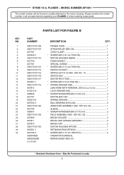
...CAP 1 SPRING WASHER 1 BALL BEARING (6201LLB 2 ARMATURE ASSEMBLY (INC. KEY NO. 20 1 SLEEVE 1 * SCREW W/WASHER (M4.8 X 75 mm 2 FIELD ASSEMBLY (INC. PLANER - POWER CORD 1 STRAIN RELIEF (6B3-2S 1 CORD CLAMP 1 * SCREW (M5 X 20 mm PAN HD 2 MOTOR HOUSING (REAR 1 FOAM GASKET 1 SPECIAL SCREW 1 ... REPAIR SHEET (REV:01) * Standard Hardware Item - May Be Purchased Locally 6 MODEL NUMBER AP1301 The model number will be found on a plate attached to the motor housing. RYOBI 13 in all correspondence regarding your PLANER or when ordering repair parts. Always mention the model number in .
...CAP 1 SPRING WASHER 1 BALL BEARING (6201LLB 2 ARMATURE ASSEMBLY (INC. KEY NO. 20 1 SLEEVE 1 * SCREW W/WASHER (M4.8 X 75 mm 2 FIELD ASSEMBLY (INC. PLANER - POWER CORD 1 STRAIN RELIEF (6B3-2S 1 CORD CLAMP 1 * SCREW (M5 X 20 mm PAN HD 2 MOTOR HOUSING (REAR 1 FOAM GASKET 1 SPECIAL SCREW 1 ... REPAIR SHEET (REV:01) * Standard Hardware Item - May Be Purchased Locally 6 MODEL NUMBER AP1301 The model number will be found on a plate attached to the motor housing. RYOBI 13 in all correspondence regarding your PLANER or when ordering repair parts. Always mention the model number in .
Repair Sheet
Page 7
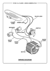
RYOBI 13 in. MODEL NUMBER AP1301 POWER GREEN LEAD CORD BRUSHES WHITE LEAD WHITE LEAD WHITE LEAD BLACK LEAD SWITCH WHITE LEAD MOTOR WIRING DIAGRAM 7 PLANER -
RYOBI 13 in. MODEL NUMBER AP1301 POWER GREEN LEAD CORD BRUSHES WHITE LEAD WHITE LEAD WHITE LEAD BLACK LEAD SWITCH WHITE LEAD MOTOR WIRING DIAGRAM 7 PLANER -


