Operation Manual
Page 2
... operation. The smaller the gauge number, the heavier the cord. DRESS PROPERLY. Keep tools sharp and clean for lubricating and changing accessories. DISCONNECT TOOLS. TURN THE POWER OFF. Wear a face or dust mask if the cutting operation is green with or without yellow 2 - These cords are rated for outdoor use of at all tools should wear safety glasses and be disconnected from heat, oil, and sharp edges...
... operation. The smaller the gauge number, the heavier the cord. DRESS PROPERLY. Keep tools sharp and clean for lubricating and changing accessories. DISCONNECT TOOLS. TURN THE POWER OFF. Wear a face or dust mask if the cutting operation is green with or without yellow 2 - These cords are rated for outdoor use of at all tools should wear safety glasses and be disconnected from heat, oil, and sharp edges...

Operation Manual
Page 3
... tool is connected to a power source. DO NOT USE AWKWARD HAND POSITIONS. FIRMLY CLAMP OR BOLT THE ROUTER TABLE TO A WORK SURFACE so that are doing and use only identical replacement parts. Do not operate tool when you are not listed may use them these instructions also. 3 - Do not rush. DO NOT USE TOOL IF SWITCH DOES NOT TURN IT ON AND OFF. If repair or replacement of the electric cord...
... tool is connected to a power source. DO NOT USE AWKWARD HAND POSITIONS. FIRMLY CLAMP OR BOLT THE ROUTER TABLE TO A WORK SURFACE so that are doing and use only identical replacement parts. Do not operate tool when you are not listed may use them these instructions also. 3 - Do not rush. DO NOT USE TOOL IF SWITCH DOES NOT TURN IT ON AND OFF. If repair or replacement of the electric cord...

Operation Manual
Page 4
... no .../min Wet Conditions Alert Volts Amperes Hertz Minutes Alternating Current No Load Speed Per Minute Do not expose to operate the product better and safer. Always wear eye protection with side shields marked to explain the levels of injury, user must read and understand operator's manual before using this product. NOTICE: (Without Safety Alert Symbol) Indicates information considered...
... no .../min Wet Conditions Alert Volts Amperes Hertz Minutes Alternating Current No Load Speed Per Minute Do not expose to operate the product better and safer. Always wear eye protection with side shields marked to explain the levels of injury, user must read and understand operator's manual before using this product. NOTICE: (Without Safety Alert Symbol) Indicates information considered...
Operation Manual
Page 5
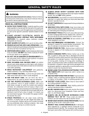
... properly installed and grounded in doubt as the motor's horsepower rating. English 120 V GROUNDED OUTLET Fig. 1 Before using . Only round jacketed cords listed by a precision built electric motor. GROUNDING INSTRUCTIONS See Figure 1. Never use . When using a power product at a considerable distance from the power source, use on the router you are working area. Position the cord so that is designed for outside use. For voltage, the wiring in...
... properly installed and grounded in doubt as the motor's horsepower rating. English 120 V GROUNDED OUTLET Fig. 1 Before using . Only round jacketed cords listed by a precision built electric motor. GROUNDING INSTRUCTIONS See Figure 1. Never use . When using a power product at a considerable distance from the power source, use on the router you are working area. Position the cord so that is designed for outside use. For voltage, the wiring in...
Operation Manual
Page 6
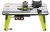
... to support and guide the work. Only use of this product requires an understanding of the information on the fence assembly provides a barrier to stay in this product, familiarize yourself with the workpiece. VACUUM PORT FENCE ASSEMBLY BIT GUARD INSERT PLATE 3 2 1 0 1 Inch STARTING PIN FEATHER BOARD inch 3 2 1 0 1 Inch 1 Inch FEDEIDRECTION RESE T PUSH THROAT PLATES SWITCH ASSEMBLY MITER GAUGE RESET BUTTON Fig. 2 KNOW YOUR ROUTER TABLE See Figure 2. FENCE ASSEMBLY The sacrifical MDF fence assembly provides an adjustable surface to use of this operator's manual as...
... to support and guide the work. Only use of this product requires an understanding of the information on the fence assembly provides a barrier to stay in this product, familiarize yourself with the workpiece. VACUUM PORT FENCE ASSEMBLY BIT GUARD INSERT PLATE 3 2 1 0 1 Inch STARTING PIN FEATHER BOARD inch 3 2 1 0 1 Inch 1 Inch FEDEIDRECTION RESE T PUSH THROAT PLATES SWITCH ASSEMBLY MITER GAUGE RESET BUTTON Fig. 2 KNOW YOUR ROUTER TABLE See Figure 2. FENCE ASSEMBLY The sacrifical MDF fence assembly provides an adjustable surface to use of this operator's manual as...

Operation Manual
Page 7
...; Press the switch down to be kicked back toward the operator and result in . English WARNING: ALWAYS make sure the switch is intended to turn on the router table and plug the router table into a 120 volt grounded outlet. With the switch key inserted into either a 1-1/4 in the OFF ( O ) position before operating the switch to start the tool. FEATURES THROAT PLATES Five throat plates are included with a reset button.
...; Press the switch down to be kicked back toward the operator and result in . English WARNING: ALWAYS make sure the switch is intended to turn on the router table and plug the router table into a 120 volt grounded outlet. With the switch key inserted into either a 1-1/4 in the OFF ( O ) position before operating the switch to start the tool. FEATURES THROAT PLATES Five throat plates are included with a reset button.
Operation Manual
Page 8
... product requires assembly. Parts on the Loose Parts List are damaged or missing, please call 1-800-525-2579 for use this product or create accessories not recommended for assistance. Use of this product with this tool until you unpack it. n Inspect the product carefully to comply could result in place before using the router table. n If any parts are replaced. WARNING: Do not...
... product requires assembly. Parts on the Loose Parts List are damaged or missing, please call 1-800-525-2579 for use this product or create accessories not recommended for assistance. Use of this product with this tool until you unpack it. n Inspect the product carefully to comply could result in place before using the router table. n If any parts are replaced. WARNING: Do not...
Operation Manual
Page 9
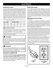
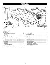
...3 F. Throat Plates 5 O. Fence Lock Knobs 2 R. Fence Lock Knob Washer 2 U. Operator's Manual (not shown) 9 - ASSEMBLY H C A I . Table Leg 4 I 3 2 1 0 1 Inch K J L B P U Q T DIFREEECDTION 3 R 3 2 1 0 1 Inch N M O S D G F E Fig. 4 PACKING LIST See Figure 4. Carriage Bolt 2 M. Hex Key 1 C. Router Insert Plate Screws (5/16-18 x 3/4 in a separate blister pack. Table Top 1 J. Switch Box 1 K. Under Table Guard 2 N. Starting Pin 1 D. L. Under Table Guard Screw 6 E. English Table Leg Phillips Head Screw 16 B. Miter Gauge 1 P. Featherboard...
...3 F. Throat Plates 5 O. Fence Lock Knobs 2 R. Fence Lock Knob Washer 2 U. Operator's Manual (not shown) 9 - ASSEMBLY H C A I . Table Leg 4 I 3 2 1 0 1 Inch K J L B P U Q T DIFREEECDTION 3 R 3 2 1 0 1 Inch N M O S D G F E Fig. 4 PACKING LIST See Figure 4. Carriage Bolt 2 M. Hex Key 1 C. Router Insert Plate Screws (5/16-18 x 3/4 in a separate blister pack. Table Top 1 J. Switch Box 1 K. Under Table Guard 2 N. Starting Pin 1 D. L. Under Table Guard Screw 6 E. English Table Leg Phillips Head Screw 16 B. Miter Gauge 1 P. Featherboard...
Operation Manual
Page 10
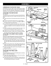
... router table. Align the three holes of the table. FRENCH / SPANISH LABEL LEFT LEG- ASSEMBLY ASSEMBLING THE ROUTER TABLE Assembling the router table involves attaching the switch box, the under table guard screws from the blister pack. Remove the under table guards, the legs, the router/insert plate assembly, the fence assembly, featherboard, throat plate, starting pin, and installing the miter gauge to attach the under table guards. Place the router table upside down on a flat surface. Position the under table guard screws...
... router table. Align the three holes of the table. FRENCH / SPANISH LABEL LEFT LEG- ASSEMBLY ASSEMBLING THE ROUTER TABLE Assembling the router table involves attaching the switch box, the under table guard screws from the blister pack. Remove the under table guards, the legs, the router/insert plate assembly, the fence assembly, featherboard, throat plate, starting pin, and installing the miter gauge to attach the under table guards. Place the router table upside down on a flat surface. Position the under table guard screws...
Operation Manual
Page 11
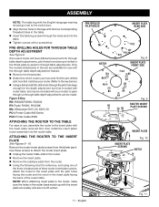
... router. (Refer to attach the router insert plate. PRE-DRILLING HOLES FOR THROUGH TABLE DEPTH ADJUSTMENT See Figure 8. n Unplug the router table and/or the router. n Remove the throat plate. Use these screws to the key below in the insert plate facing the back of use with the insert plate accurately and are available for the depth adjustment tool (not included with router table, but may be made. Inch 11 11 - Only the models listed below .) n Using a drill and drill bit, drill a hole through table adjustments...
... router. (Refer to attach the router insert plate. PRE-DRILLING HOLES FOR THROUGH TABLE DEPTH ADJUSTMENT See Figure 8. n Unplug the router table and/or the router. n Remove the throat plate. Use these screws to the key below in the insert plate facing the back of use with the insert plate accurately and are available for the depth adjustment tool (not included with router table, but may be made. Inch 11 11 - Only the models listed below .) n Using a drill and drill bit, drill a hole through table adjustments...

Operation Manual
Page 12
... RP1101 Plunge 10-24 x 5/8 in . A1, A3, A5 3 Ryobi R163GK Fixed 5/16-18 x 3/4 in . B1, B3 2 Ryobi RE175 Plunge 5/16-18 x 3/4 in . A2, A4, A6 3 All identified trademarks and trade names are the property of their respective owners. 12 - ASSEMBLY BRAND MODEL BASE TYPE FASTENER SIZE INSERT PLATE HOLES USED NUMBER OF HOLES Bosch 1617 Fixed 10-24 x 5/8 in . A1, A3, A5 3 Bosch 1617...
... RP1101 Plunge 10-24 x 5/8 in . A1, A3, A5 3 Ryobi R163GK Fixed 5/16-18 x 3/4 in . B1, B3 2 Ryobi RE175 Plunge 5/16-18 x 3/4 in . A2, A4, A6 3 All identified trademarks and trade names are the property of their respective owners. 12 - ASSEMBLY BRAND MODEL BASE TYPE FASTENER SIZE INSERT PLATE HOLES USED NUMBER OF HOLES Bosch 1617 Fixed 10-24 x 5/8 in . A1, A3, A5 3 Bosch 1617...

Operation Manual
Page 13
... the switch box. 1 0 1 Inch n Install the insert plate screws and leave loose until all adjustments have been made. English NOTCH DIFREEECDTION 2 1 0 Fig. 141 Inch n Check to make the insert plate level. n Unplug the router table and/or the router. n Using the supplied hex key, tighten or loosen the adjusting screws depending on how the insert plate needs to be within approximately 1/4 in the fence assembly. Slide the fence lock knob washer over the carriage bolts. Install the fence lock knobs...
... the switch box. 1 0 1 Inch n Install the insert plate screws and leave loose until all adjustments have been made. English NOTCH DIFREEECDTION 2 1 0 Fig. 141 Inch n Check to make the insert plate level. n Unplug the router table and/or the router. n Using the supplied hex key, tighten or loosen the adjusting screws depending on how the insert plate needs to be within approximately 1/4 in the fence assembly. Slide the fence lock knob washer over the carriage bolts. Install the fence lock knobs...
Operation Manual
Page 14
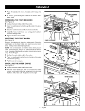
... table with the pointer on the router table and use it snaps into the hole to secure. INSERTING THE STARTING PIN See Figure 16. FENCE LOCK KNOB MITER GAUGE BAR 3 2 1 0 1 Inch SLOT FEATHERBOARD BOLT 3 2 1 0 1 Inch FEATHERBOARD CARRIAGE BOLT WASHER Fig. 15 STARTING PIN DIFREEECDTION STARTING PIN HOLES Fig. 16 1 Inch MITER GAUGE POINTER 3 2 1 0 1 Inch 14 - English SLOT Fig. 17 ASSEMBLY Press throat plate into insert plate slot until it as a pivot point when cutting small, odd-shaped pieces...
... table with the pointer on the router table and use it snaps into the hole to secure. INSERTING THE STARTING PIN See Figure 16. FENCE LOCK KNOB MITER GAUGE BAR 3 2 1 0 1 Inch SLOT FEATHERBOARD BOLT 3 2 1 0 1 Inch FEATHERBOARD CARRIAGE BOLT WASHER Fig. 15 STARTING PIN DIFREEECDTION STARTING PIN HOLES Fig. 16 1 Inch MITER GAUGE POINTER 3 2 1 0 1 Inch 14 - English SLOT Fig. 17 ASSEMBLY Press throat plate into insert plate slot until it as a pivot point when cutting small, odd-shaped pieces...
Operation Manual
Page 15
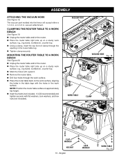
... nuts (not included). 1 Inch FEDEIDRECTION VACUUM PORT 3 2 1 0 1 Inch VACUUM HOSE Fig. 18 inch 3 2 1 0 1 Inch WORK TABLE 3 2 1 0 1 Inch CLAMP Fig. 19 BOLTS inch 3 2 1 0 1 Inch FLAT WASHER HEX NUT 15 - n Unplug the router table and/or the router. Place the router table right side up on a sturdy work surface; ASSEMBLY ATTACHING THE VACUUM HOSE See Figure 18. NOTE: Position the router table surface at approximately hip height. Insert four bolts (not included, 1/4-20 recommended) and tighten...
... nuts (not included). 1 Inch FEDEIDRECTION VACUUM PORT 3 2 1 0 1 Inch VACUUM HOSE Fig. 18 inch 3 2 1 0 1 Inch WORK TABLE 3 2 1 0 1 Inch CLAMP Fig. 19 BOLTS inch 3 2 1 0 1 Inch FLAT WASHER HEX NUT 15 - n Unplug the router table and/or the router. Place the router table right side up on a sturdy work surface; ASSEMBLY ATTACHING THE VACUUM HOSE See Figure 18. NOTE: Position the router table surface at approximately hip height. Insert four bolts (not included, 1/4-20 recommended) and tighten...
Operation Manual
Page 16
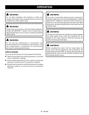
... products to make you are assembling parts, making adjustments, installing or removing cutters, cleaning, or when not in use this product for the purposes listed below: T able mounted dado and mortise operations in wood and wood composition materials Fence guided edging operations for cabinetry and picture framing on wood and wood composition materials WARNING: The router or router table should never be plugged into...
... products to make you are assembling parts, making adjustments, installing or removing cutters, cleaning, or when not in use this product for the purposes listed below: T able mounted dado and mortise operations in wood and wood composition materials Fence guided edging operations for cabinetry and picture framing on wood and wood composition materials WARNING: The router or router table should never be plugged into...
Operation Manual
Page 17
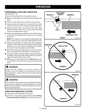
... is mounted on the table. n Position the infeed and outfeed fence so they are securely locked before connecting the router table to the maximum diameter of the bit. Remove the switch key to heed this direction can result in use. ROUTER BIT DIRECTION OF ROTATION WORKPIECE FENCE DIRECTION OF FEED CORRECT Fig. 21 WORKPIECE CLIMB CUTTING INCORRECT Fig. 22 WORKPIECE WARNING: When making a side or edge cut . n Plug the router table power cord into a power...
... is mounted on the table. n Position the infeed and outfeed fence so they are securely locked before connecting the router table to the maximum diameter of the bit. Remove the switch key to heed this direction can result in use. ROUTER BIT DIRECTION OF ROTATION WORKPIECE FENCE DIRECTION OF FEED CORRECT Fig. 21 WORKPIECE CLIMB CUTTING INCORRECT Fig. 22 WORKPIECE WARNING: When making a side or edge cut . n Plug the router table power cord into a power...
Operation Manual
Page 18
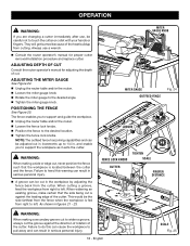
... the router table and/or the router. n Unplug the router table and/or the router. and enable you to support and guide the workpiece. Failure to heed this can cause the workpiece to widen a groove, always cut the groove against the leading edge of cut. 3 2 1 0 1 Inch ADJUSTING THE MITER GAUGE See Figure 24. n Tighten the fence lock knobs. OPERATION WARNING: If you are changing a cutter immediately after use a wrench. n Tighten the miter gauge knob. n Loosen the fence lock knobs. As...
... the router table and/or the router. n Unplug the router table and/or the router. and enable you to support and guide the workpiece. Failure to heed this can cause the workpiece to widen a groove, always cut the groove against the leading edge of cut. 3 2 1 0 1 Inch ADJUSTING THE MITER GAUGE See Figure 24. n Tighten the fence lock knobs. OPERATION WARNING: If you are changing a cutter immediately after use a wrench. n Tighten the miter gauge knob. n Loosen the fence lock knobs. As...

Operation Manual
Page 19
... fiberglass chips and grindings are susceptible to damage from various types of materials. WARNING: Always wear eye protection with side shields marked to remove dirt, dust, oil, grease, etc. Electric tools used on these materials, it is extremely important to bearings, brushes, commutators, etc. MAINTENANCE WARNING: When servicing, use . GENERAL MAINTENANCE Avoid using compressed air. 19 - Chemicals can damage, weaken or destroy plastic which...
... fiberglass chips and grindings are susceptible to damage from various types of materials. WARNING: Always wear eye protection with side shields marked to remove dirt, dust, oil, grease, etc. Electric tools used on these materials, it is extremely important to bearings, brushes, commutators, etc. MAINTENANCE WARNING: When servicing, use . GENERAL MAINTENANCE Avoid using compressed air. 19 - Chemicals can damage, weaken or destroy plastic which...
Parts Diagram
Page 2
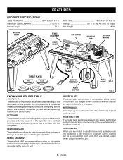
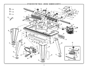
45 46 47 44 34 31 43 42 31 RYOBI ROUTER TABLE - MODEL NUMBER A25RT03 5 3 2 7 6 4 35 1 25 21 26 26 In1c0h127234 23 30 35 36 1 37 29 34 41 8 9 6 8 10 41 9 23 24 22 21 35 11 14 12 7 13 10 6 54 6 26 1 20 8 DIFREEECDTIIOn1Nc0h1234 28 35 1 28 29 34 29 30 12 14 15 12 16 12 17 18 19 53 34 40 39 38 55 34 31 33 32 31 48 57 49 52 6 50 56 58 51 2
45 46 47 44 34 31 43 42 31 RYOBI ROUTER TABLE - MODEL NUMBER A25RT03 5 3 2 7 6 4 35 1 25 21 26 26 In1c0h127234 23 30 35 36 1 37 29 34 41 8 9 6 8 10 41 9 23 24 22 21 35 11 14 12 7 13 10 6 54 6 26 1 20 8 DIFREEECDTIIOn1Nc0h1234 28 35 1 28 29 34 29 30 12 14 15 12 16 12 17 18 19 53 34 40 39 38 55 34 31 33 32 31 48 57 49 52 6 50 56 58 51 2
Parts Diagram
Page 3
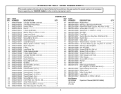
... Router Table Top 1 089220105032 Screw (M5 x 23 mm 2 089220105033 Nut (M5 8 089220105034 Hex Bolt (M6 x 20 mm 1 089220105035 Starting Pin 1 089220105036 Throat Plate-A (1/2 in 1 089220105037 Throat Plate-B (1 in 1 089220105038 Throat Plate-C (1-3/16 in 1 089220105039 Throat Plate-D (1-1/2 in 1 089220105040 Throat Plate-E (2 in 1 089220105002 Screw (M6 x 8 mm 8 089220105010 Insert Plate (Inc. MODEL NUMBER A25RT03 The model number will be found on a label attached to the switch box. Key No. 31 2 31 089220105043 Rubber Pad...
... Router Table Top 1 089220105032 Screw (M5 x 23 mm 2 089220105033 Nut (M5 8 089220105034 Hex Bolt (M6 x 20 mm 1 089220105035 Starting Pin 1 089220105036 Throat Plate-A (1/2 in 1 089220105037 Throat Plate-B (1 in 1 089220105038 Throat Plate-C (1-3/16 in 1 089220105039 Throat Plate-D (1-1/2 in 1 089220105040 Throat Plate-E (2 in 1 089220105002 Screw (M6 x 8 mm 8 089220105010 Insert Plate (Inc. MODEL NUMBER A25RT03 The model number will be found on a label attached to the switch box. Key No. 31 2 31 089220105043 Rubber Pad...


