User Guide
Page 1
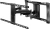
FULL MOTION RF-HTLF23 ASSEMBLY GUIDE Before using your new product, please read these instructions to 75" TV WALL MOUNT - 40" to prevent any damage.
FULL MOTION RF-HTLF23 ASSEMBLY GUIDE Before using your new product, please read these instructions to 75" TV WALL MOUNT - 40" to prevent any damage.
User Guide
Page 2
...or use . • The weight of a high-quality Rocketfish product. Rocketfish is designed ONLY to be capable of supporting five times the weight of the installation, contact Customer Service or call a qualified contractor. Call 1-800-620-2790 (U.S. IMPORTANT SAFETY INSTRUCTIONS SAVE THESE INSTRUCTIONS &#...USE ONLY. • The wall must not exceed 100 lbs. (45.3 kg). • This product contains small items that could be a choking hazard if swallowed. and Canada) Your RF-HTLF23 represents the state of the art in TV wall-mount design and is designed for reliable and trouble-free...
...or use . • The weight of a high-quality Rocketfish product. Rocketfish is designed ONLY to be capable of supporting five times the weight of the installation, contact Customer Service or call a qualified contractor. Call 1-800-620-2790 (U.S. IMPORTANT SAFETY INSTRUCTIONS SAVE THESE INSTRUCTIONS &#...USE ONLY. • The wall must not exceed 100 lbs. (45.3 kg). • This product contains small items that could be a choking hazard if swallowed. and Canada) Your RF-HTLF23 represents the state of the art in TV wall-mount design and is designed for reliable and trouble-free...
User Guide
Page 3
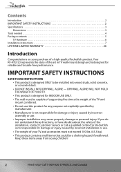
Call 1-800-620-2790 (U.S. and Canada) 3 to 75 in. (101.6 cm to 190.5 cm) diagonal • Overall dimensions (H × W): 17.7 × 25.1 in . RF-HTLF23 Specifications • Maximum TV weight: 100 lbs. (45.3 kg) • Screen size: From 40 in . (45 cm × 63.9 cm) • Wall-mount weight: 18.8 lbs. (8.5 kg) • For customer service, call: 1-800-620-2790 Dimensions 25.14" (63.9 cm) 17.72" (45 cm) Need help?
Call 1-800-620-2790 (U.S. and Canada) 3 to 75 in. (101.6 cm to 190.5 cm) diagonal • Overall dimensions (H × W): 17.7 × 25.1 in . RF-HTLF23 Specifications • Maximum TV weight: 100 lbs. (45.3 kg) • Screen size: From 40 in . (45 cm × 63.9 cm) • Wall-mount weight: 18.8 lbs. (8.5 kg) • For customer service, call: 1-800-620-2790 Dimensions 25.14" (63.9 cm) 17.72" (45 cm) Need help?
User Guide
Page 5
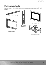
and Canada) 5 RF-HTLF23 Package contents Make sure that you have all the hardware necessary to assemble your new TV wall mount: 04 Horizontal bracket (2) 08 Wall plate (1) 05 Vertical bracket (1) 07 Template (1) 11 Arm assembly (1) Need help? Call 1-800-620-2790 (U.S.
and Canada) 5 RF-HTLF23 Package contents Make sure that you have all the hardware necessary to assemble your new TV wall mount: 04 Horizontal bracket (2) 08 Wall plate (1) 05 Vertical bracket (1) 07 Template (1) 11 Arm assembly (1) Need help? Call 1-800-620-2790 (U.S.
User Guide
Page 7
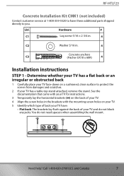
RF-HTLF23 Concrete Installation Kit CMK1 (not included) Contact customer service at 1-800-359-5520 to have : • Flat back: The brackets lay flush against the back of your TV and do not need spacers when assembling the wall mount. Call 1-800-620-2790 (U.S. See the documentation that came with the mounting.... Lbl. You do not block any jacks. Hardware # C1 Lag screw 5/16 × 2 3/4 in. 4 C2 Washer 5/16 in the brackets with your TV for instructions. 3 Temporarily lay the horizontal brackets (04) on a cushioned, clean surface to you. Need help? and Canada) 7
RF-HTLF23 Concrete Installation Kit CMK1 (not included) Contact customer service at 1-800-359-5520 to have : • Flat back: The brackets lay flush against the back of your TV and do not need spacers when assembling the wall mount. Call 1-800-620-2790 (U.S. See the documentation that came with the mounting.... Lbl. You do not block any jacks. Hardware # C1 Lag screw 5/16 × 2 3/4 in. 4 C2 Washer 5/16 in the brackets with your TV for instructions. 3 Temporarily lay the horizontal brackets (04) on a cushioned, clean surface to you. Need help? and Canada) 7
User Guide
Page 9
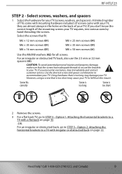
...) for your TV requires, test various sizes by hand threading the screws. Need help? CAUTION: To avoid potential personal injuries and property damage, make sure that is too short 2 Remove the screws. 3 For a flat back TV, go to fall from the mount. Using hardware that the screws have adequate threads ... number of TVs come with mounting hardware included. (If screws came with your TV, they are almost always in the holes on page 10. -ORFor an irregular or obstructed back, go to your TV. Screw fits correctly Screw is too long Screw is too long may cause your TV. RF-HTLF23 STEP...
...) for your TV requires, test various sizes by hand threading the screws. Need help? CAUTION: To avoid potential personal injuries and property damage, make sure that is too short 2 Remove the screws. 3 For a flat back TV, go to fall from the mount. Using hardware that the screws have adequate threads ... number of TVs come with mounting hardware included. (If screws came with your TV, they are almost always in the holes on page 10. -ORFor an irregular or obstructed back, go to your TV. Screw fits correctly Screw is too long Screw is too long may cause your TV. RF-HTLF23 STEP...
User Guide
Page 11
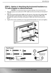
Make sure that the brackets are level. 3 Tighten the screws until they are snug against the brackets. RF-HTLF23 STEP 3 - Call 1-800-620-2790 (U.S. and Canada) 11 Insert the screws you selected in STEP 2 (03) over the screw holes on the back of...(4) 04 Horizontal brackets (2) OR 03 Spacers (4) Need help? Do not over the holes in STEP 2 (01) through the washers, brackets, and spacers. Option 2: Attaching the horizontal brackets to a TV with irregular or obstructed back CAUTION: To avoid personal injury or property damage, do not use power tools. 1 Place the spacers you selected in...
Make sure that the brackets are level. 3 Tighten the screws until they are snug against the brackets. RF-HTLF23 STEP 3 - Call 1-800-620-2790 (U.S. and Canada) 11 Insert the screws you selected in STEP 2 (03) over the screw holes on the back of...(4) 04 Horizontal brackets (2) OR 03 Spacers (4) Need help? Do not over the holes in STEP 2 (01) through the washers, brackets, and spacers. Option 2: Attaching the horizontal brackets to a TV with irregular or obstructed back CAUTION: To avoid personal injury or property damage, do not use power tools. 1 Place the spacers you selected in...
User Guide
Page 13
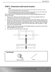
...be placed above items placed on determining where to drill your holes, visit our online height-finder at: http://mf1.bestbuy.selectionassistant.com/index.php/heightfinder The center of your TV should also be placed on the wall. RF-HTLF23 STEP 5 - This is measurement a. 2 Measure the distance from a seated... position (normally, 40 to mark this spot on the wall. Your TV should be on the wall. 4 Use a pencil to 60 inches from the bottom of the four mounting screw holes. The total...
...be placed above items placed on determining where to drill your holes, visit our online height-finder at: http://mf1.bestbuy.selectionassistant.com/index.php/heightfinder The center of your TV should also be placed on the wall. RF-HTLF23 STEP 5 - This is measurement a. 2 Measure the distance from a seated... position (normally, 40 to mark this spot on the wall. Your TV should be on the wall. 4 Use a pencil to 60 inches from the bottom of the four mounting screw holes. The total...

User Guide
Page 14
...; 8.9 cm). STEP 6 - Option 1: Installing on a wood stud wall Note: Drywall covering the wall must not exceed 5/8" (16 mm). 1 Locate the stud, then verify the center of the stud with an edge-to edge stud finder 7/32" wood drill bit Tape Drill 1/2" socket wrench 14 Need help? and Canada) Minimum wood stud size: nominal 2 × 4 in...
...; 8.9 cm). STEP 6 - Option 1: Installing on a wood stud wall Note: Drywall covering the wall must not exceed 5/8" (16 mm). 1 Locate the stud, then verify the center of the stud with an edge-to edge stud finder 7/32" wood drill bit Tape Drill 1/2" socket wrench 14 Need help? and Canada) Minimum wood stud size: nominal 2 × 4 in...

User Guide
Page 15
and Canada) 15 Call 1-800-620-2790 (U.S. Tape the template to the wall. 2 3/4 in (69 mm) 7/32 in (5.5 mm) 07 4 Drill four pilot holes through the template to a depth of the wall plate template (07) at the height you determined in . (7 cm) Need help? RF-HTLF23 3 Align the center of 2 3/4 in. (7 cm) using a 7/32 in. (5.5 mm) diameter drill bit, then remove the template. 2 3/4 in the previous step and make sure that it is level.
and Canada) 15 Call 1-800-620-2790 (U.S. Tape the template to the wall. 2 3/4 in (69 mm) 7/32 in (5.5 mm) 07 4 Drill four pilot holes through the template to a depth of the wall plate template (07) at the height you determined in . (7 cm) Need help? RF-HTLF23 3 Align the center of 2 3/4 in. (7 cm) using a 7/32 in. (5.5 mm) diameter drill bit, then remove the template. 2 3/4 in the previous step and make sure that it is level.
User Guide
Page 17
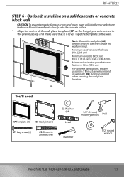
RF-HTLF23 STEP 6 - Tape the template to the wall. Call 1-800-620-2790 (U.S. Minimum solid concrete thickness: 8 in . (20.3 × 20.3 × 40.6 cm). Minimum concrete block size: 8 × 8 × 16 in . (20.3 cm). Mount the wall plate directly...the blocks. Note: Mount the wall plate (08) directly onto the concrete surface (no wall covering). and Canada) 17 Option 2: Installing on a solid concrete...need 07 Template (1) 08 Wall plate (1) C1 Lag screw (4) C3 Concrete anchors (04) C2 Washer (04) Level Hammer 3/8" (10 mm) masonry drill bit Drill Tape 1/2" socket wrench Need help...
RF-HTLF23 STEP 6 - Tape the template to the wall. Call 1-800-620-2790 (U.S. Minimum solid concrete thickness: 8 in . (20.3 × 20.3 × 40.6 cm). Minimum concrete block size: 8 × 8 × 16 in . (20.3 cm). Mount the wall plate directly...the blocks. Note: Mount the wall plate (08) directly onto the concrete surface (no wall covering). and Canada) 17 Option 2: Installing on a solid concrete...need 07 Template (1) 08 Wall plate (1) C1 Lag screw (4) C3 Concrete anchors (04) C2 Washer (04) Level Hammer 3/8" (10 mm) masonry drill bit Drill Tape 1/2" socket wrench Need help...

User Guide
Page 18
Call 1-800-620-2790 (U.S. C3 18 Need help? and Canada) 2 Drill pilot holes to a depth of 3 in. (7.6 cm) using a 3/8 in. (10 mm) diameter masonry drill bit, then remove the template. 3 in. (76 mm) 07 3 Insert the concrete wall anchors (C3) (see Concrete Installation Kit CMK1 (not included) on page 7) into the pilot holes and use a hammer to make sure that the anchors are flush with the concrete surface.
Call 1-800-620-2790 (U.S. C3 18 Need help? and Canada) 2 Drill pilot holes to a depth of 3 in. (7.6 cm) using a 3/8 in. (10 mm) diameter masonry drill bit, then remove the template. 3 in. (76 mm) 07 3 Insert the concrete wall anchors (C3) (see Concrete Installation Kit CMK1 (not included) on page 7) into the pilot holes and use a hammer to make sure that the anchors are flush with the concrete surface.
User Guide
Page 19
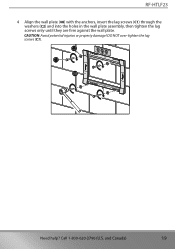
Call 1-800-620-2790 (U.S. RF-HTLF23 4 Align the wall plate (08) with the anchors, insert the lag screws (C1) through the washers (C2) and into the holes in the wall plate assembly, then tighten the lag screws only until they are firm against the wall plate. C2 C1 08 Need help? DO NOT over-tighten the lag screws (C1). CAUTION: Avoid potential injuries or property damage! and Canada) 19
Call 1-800-620-2790 (U.S. RF-HTLF23 4 Align the wall plate (08) with the anchors, insert the lag screws (C1) through the washers (C2) and into the holes in the wall plate assembly, then tighten the lag screws only until they are firm against the wall plate. C2 C1 08 Need help? DO NOT over-tighten the lag screws (C1). CAUTION: Avoid potential injuries or property damage! and Canada) 19
User Guide
Page 21
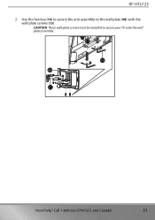
Call 1-800-620-2790 (U.S. and Canada) 21 CAUTION: These wall plate screws must be installed to the wall plate (08) with the wall plate screws (13). RF-HTLF23 2 Use the hex key (14) to secure the arm assembly to secure your TV onto the wall plate assembly. 13 14 08 11 Need help?
Call 1-800-620-2790 (U.S. and Canada) 21 CAUTION: These wall plate screws must be installed to the wall plate (08) with the wall plate screws (13). RF-HTLF23 2 Use the hex key (14) to secure the arm assembly to secure your TV onto the wall plate assembly. 13 14 08 11 Need help?
User Guide
Page 23
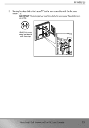
IMPORTANT: The locking screw must be installed to the arm assembly with this step. 12 14 Need help? You may need assistance 11 with the locking screw (12). RF-HTLF23 2 Use the hex key (14) to lock your TV to secure your TV onto the arm assembly. 05 HEAVY! and Canada) 23 Call 1-800-620-2790 (U.S.
IMPORTANT: The locking screw must be installed to the arm assembly with this step. 12 14 Need help? You may need assistance 11 with the locking screw (12). RF-HTLF23 2 Use the hex key (14) to lock your TV to secure your TV onto the arm assembly. 05 HEAVY! and Canada) 23 Call 1-800-620-2790 (U.S.

User Guide
Page 24
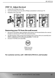
Tension knob 14 24 Need help? Call 1-800-620-2790 (U.S. and Canada) Managing cables • Fully extend the arm assembly (11) to provide enough slack, then routing cables along the arms and inserting them into the channels on the arms to provide a clean look to keep your installation. 11 STEP 10 - Adjust tilt Note: After your TV is in place, tighten the tilt tension knob to prevent unwanted movement. • Loosen the tension knob with your fingers or the hex key (14), adjust the tilt angle, then tighten the knob to your TV in place. STEP 9 -
Tension knob 14 24 Need help? Call 1-800-620-2790 (U.S. and Canada) Managing cables • Fully extend the arm assembly (11) to provide enough slack, then routing cables along the arms and inserting them into the channels on the arms to provide a clean look to keep your installation. 11 STEP 10 - Adjust tilt Note: After your TV is in place, tighten the tilt tension knob to prevent unwanted movement. • Loosen the tension knob with your fingers or the hex key (14), adjust the tilt angle, then tighten the knob to your TV in place. STEP 9 -
User Guide
Page 25
... cables, then pull down the release cord located below the vertical bracket to unlock your TV from the vertical bracket. 2 Use the hex key (14)to the arm assembly on page 22). 3 Lift your TV to remove the locking screw (12) from the arm assembly (see STEP 8 - RF-HTLF23 STEP 10 - Adjust the level 1 Loosen the locking screw (12). 2 Turn...
... cables, then pull down the release cord located below the vertical bracket to unlock your TV from the vertical bracket. 2 Use the hex key (14)to the arm assembly on page 22). 3 Lift your TV to remove the locking screw (12) from the arm assembly (see STEP 8 - RF-HTLF23 STEP 10 - Adjust the level 1 Loosen the locking screw (12). 2 Turn...

User Guide
Page 26
... Buy online website (www.bestbuy.com or www.bestbuy.ca), please take your Rocketfish Product during the Warranty Period. and Canada) This warranty lasts as long as power surges 26 Need help? This warranty is packaged with the Product. How long does the coverage last? This warranty does not cover: • Customer instruction/education • Installation • Set up adjustments...
... Buy online website (www.bestbuy.com or www.bestbuy.ca), please take your Rocketfish Product during the Warranty Period. and Canada) This warranty lasts as long as power surges 26 Need help? This warranty is packaged with the Product. How long does the coverage last? This warranty does not cover: • Customer instruction/education • Installation • Set up adjustments...
User Guide
Page 27
... in ). • Damage due to incorrect operation or maintenance • Connection to an incorrect voltage or power supply • Attempted repair by any person not authorized by Rocketfish to service the Product • Products sold "as is a trademark of Best Buy and its affiliated companies. *Distributed by any part of the product • Display panels containing up to five (5) pixel...
... in ). • Damage due to incorrect operation or maintenance • Connection to an incorrect voltage or power supply • Attempted repair by any person not authorized by Rocketfish to service the Product • Products sold "as is a trademark of Best Buy and its affiliated companies. *Distributed by any part of the product • Display panels containing up to five (5) pixel...
Warranty Sheet
Page 1
...: • Customer instruction/education • Installation • Set up adjustments • Cosmetic damage • Damage due to weather, lightning, and other acts of the display size or up to three (3) pixel failures (dots that are not returned to an incorrect voltage or power supply • Attempted repair by any part of Best Buy and its sole option): (1) repair the Product with new or rebuilt...
...: • Customer instruction/education • Installation • Set up adjustments • Cosmetic damage • Damage due to weather, lightning, and other acts of the display size or up to three (3) pixel failures (dots that are not returned to an incorrect voltage or power supply • Attempted repair by any part of Best Buy and its sole option): (1) repair the Product with new or rebuilt...

