Owners Manual
Page 4
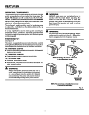
...use brake fluids, gasoline, petroleum-based products, or any solvents to a live terminal. Inspect for and remove all fences and auxiliary tables before transporting saw blade. Stay out of the motor could ignite fumes. Inspect TOOL CORDS periodically. A push stick is ... tool is equipped with the accessory. DOUBLE CHECK ALL SETUPS. Have defective switches replaced by a qualified service technician at approximately waist height. NEVER OPERATE THE SAw ON THE FLOOR. GUARD AGAINST KICKBACK. The maximum blade capacity of drugs, alcohol, or any...
...use brake fluids, gasoline, petroleum-based products, or any solvents to a live terminal. Inspect for and remove all fences and auxiliary tables before transporting saw blade. Stay out of the motor could ignite fumes. Inspect TOOL CORDS periodically. A push stick is ... tool is equipped with the accessory. DOUBLE CHECK ALL SETUPS. Have defective switches replaced by a qualified service technician at approximately waist height. NEVER OPERATE THE SAw ON THE FLOOR. GUARD AGAINST KICKBACK. The maximum blade capacity of drugs, alcohol, or any...
Owners Manual
Page 11
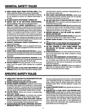
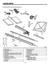
... 45 2-1/4 in . Cutting Depth at 0 3-1/4 in . RIP FENCE MITER GAUGE GROOVE RIP FENCE SCALE TABLE EXTENSION MITER gauge RIP FENCE STORAGE BRACKETS FRONT bevel RAIL ADJUSTING 45 HANDWHEEL BEVEL SCALE LOCKING HANDLE SWITCH ASSEMBLY hEight ADJUSTING HANDWHEEL HEIGHT LOCK KNOB bevel LOCK KNOB push stick 11 BLADE AND WRENCH STORAGE MITER GAUGE STORAGE...
... 45 2-1/4 in . Cutting Depth at 0 3-1/4 in . RIP FENCE MITER GAUGE GROOVE RIP FENCE SCALE TABLE EXTENSION MITER gauge RIP FENCE STORAGE BRACKETS FRONT bevel RAIL ADJUSTING 45 HANDWHEEL BEVEL SCALE LOCKING HANDLE SWITCH ASSEMBLY hEight ADJUSTING HANDWHEEL HEIGHT LOCK KNOB bevel LOCK KNOB push stick 11 BLADE AND WRENCH STORAGE MITER GAUGE STORAGE...
Owners Manual
Page 12
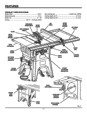
... give the operator additional support when cutting wide workpieces. RIP FENCE - When in the grooves on the tool and in personal injury. TABLE EXTENSION - HEIGHT ADJUSTING HANDWHEEL/ HEIGHT LOCK KNOB - The bevel adjusting handwheel, located on the front of the cabinet, is higher than the saw is secured with a 36... blade.The bevel lock knob locks the angle setting of the saw blade teeth and becomes a riving knife. FEATURES KNOW YOUR TABLE SAW See Figure 5. BLADE GUARD - The height lock knob locks the height setting of the blade guard assembly, slightly thinner than the saw...
... give the operator additional support when cutting wide workpieces. RIP FENCE - When in the grooves on the tool and in personal injury. TABLE EXTENSION - HEIGHT ADJUSTING HANDWHEEL/ HEIGHT LOCK KNOB - The bevel adjusting handwheel, located on the front of the cabinet, is higher than the saw is secured with a 36... blade.The bevel lock knob locks the angle setting of the saw blade teeth and becomes a riving knife. FEATURES KNOW YOUR TABLE SAW See Figure 5. BLADE GUARD - The height lock knob locks the height setting of the blade guard assembly, slightly thinner than the saw...
Owners Manual
Page 13
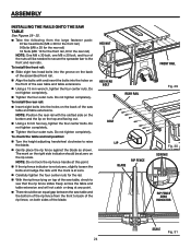
...the cover is surrounded by children and others. Fig. 6 13 This saw : Press the switch button down to position work for all through the table and is not shown in the Operation section of this warning may cause the workpiece to be removed to turn the switch off ( O ). WARNING: ALWAYS... called the throat plate. POWER SWITCH See Figure 6. The blade guard assembly includes: riving knife/spreader/splitter, anti-kickback pawls, and blade guard. The height of the blade is very important to be kicked back toward the operator and result in a safe place.
...the cover is surrounded by children and others. Fig. 6 13 This saw : Press the switch button down to position work for all through the table and is not shown in the Operation section of this warning may cause the workpiece to be removed to turn the switch off ( O ). WARNING: ALWAYS... called the throat plate. POWER SWITCH See Figure 6. The blade guard assembly includes: riving knife/spreader/splitter, anti-kickback pawls, and blade guard. The height of the blade is very important to be kicked back toward the operator and result in a safe place.
Owners Manual
Page 15
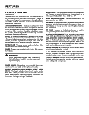
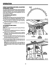
Rip Fence 1 E. Push Stick 1 H. Blade Wrench, closed end 1 J. Rail Connector Bar 3 N. Table Extensions 2 O. Front End Cap (left and right 2 Not shown: T. Height Adjusting Handwheel, Washer, and Knob...... 1 F. Small (contents noted on pack 1 S. Miter Gauge 1 D. Bevel Adjusting Handwheel, Washer, and Knob........ 1 G. ... pack 1 15 Fastener Pack - Front Rail 2 M. Spreader Bar 1 P. LOOSE PARTS The following items are included with the table saw: A G B C E, F N Q D K L K O P M S L J HI R Fig. 8 A. Anti-Kickback Pawls 1 C. Blade Guard 1 B.
Rip Fence 1 E. Push Stick 1 H. Blade Wrench, closed end 1 J. Rail Connector Bar 3 N. Table Extensions 2 O. Front End Cap (left and right 2 Not shown: T. Height Adjusting Handwheel, Washer, and Knob...... 1 F. Small (contents noted on pack 1 S. Miter Gauge 1 D. Bevel Adjusting Handwheel, Washer, and Knob........ 1 G. ... pack 1 15 Fastener Pack - Front Rail 2 M. Spreader Bar 1 P. LOOSE PARTS The following items are included with the table saw: A G B C E, F N Q D K L K O P M S L J HI R Fig. 8 A. Anti-Kickback Pawls 1 C. Blade Guard 1 B.
Owners Manual
Page 24
... rail with and insert the bolts into the holes on the front of the saw table and table extensions. Using a 13 mm wrench, tighten the four center nuts. To check the table and rail position: Turn the height adjusting handwheel clockwise to the front and rear rails. Do not tighten completely. hex... M8 x 30 bolt, one M8 x 20 bolt, and four of the nuts will not catch or drag at zero on the back of the saw table and table extensions. To install the rear rail: Insert eight bolts into the groove on the back of the assembled front rail. Align the...
... rail with and insert the bolts into the holes on the front of the saw table and table extensions. Using a 13 mm wrench, tighten the four center nuts. To check the table and rail position: Turn the height adjusting handwheel clockwise to the front and rear rails. Do not tighten completely. hex... M8 x 30 bolt, one M8 x 20 bolt, and four of the nuts will not catch or drag at zero on the back of the saw table and table extensions. To install the rear rail: Insert eight bolts into the groove on the back of the assembled front rail. Align the...
Owners Manual
Page 33
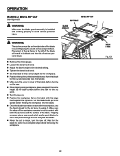
..., the blade should be at 90° to the saw table and the bevel indicator should be square with the saw table. (See the Adjustments section of the blade are below the top surface. Raise the blade by unlocking the height adjusting handwheel and turning it will go, the blade should be... at a 45° angle to the saw table and the bevel indicator should point to 45°. When the saw blade is tilted...
..., the blade should be at 90° to the saw table and the bevel indicator should be square with the saw table. (See the Adjustments section of the blade are below the top surface. Raise the blade by unlocking the height adjusting handwheel and turning it will go, the blade should be... at a 45° angle to the saw table and the bevel indicator should point to 45°. When the saw blade is tilted...
Owners Manual
Page 36
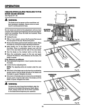
...before beginning any operation. 36 rear panel Fig. 54 MITER gauge GROOVE Fig. 55 MITER gauge GROOVE Fig. 56 Raise the blade by turning the height adjusting handwheel. Mark beside one of the blade teeth at the back. Move the combination square to the combination square, push or... from kickback, align the rip fence to the blade following any bolts for this adjustment until you have checked with the front of the saw table and the side of the blade. Remove the panel. Remove the blade guard and anti-kickback pawls. Retighten the bolts. OPERATION heeling (...
...before beginning any operation. 36 rear panel Fig. 54 MITER gauge GROOVE Fig. 55 MITER gauge GROOVE Fig. 56 Raise the blade by turning the height adjusting handwheel. Mark beside one of the blade teeth at the back. Move the combination square to the combination square, push or... from kickback, align the rip fence to the blade following any bolts for this adjustment until you have checked with the front of the saw table and the side of the blade. Remove the panel. Remove the blade guard and anti-kickback pawls. Retighten the bolts. OPERATION heeling (...
Owners Manual
Page 38
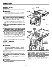
...and the hand farthest from the blade for the cut and securely lock the handle. When ripping a long workpiece, place a support the same height as the table surface behind the saw off . WARNING: Make sure the blade guard assembly is made , turn the saw for the workpiece. Set the ... the cut is clear of the workpiece remains in solid contact with both hands on the table with both the rip fence and the surface of the table. making a RIP cut See Figure 59. SCALE Fig. 59 HEight ADJUSTING HANDWHEEL Fig. 60 Remove the rip fence. Set the blade to...
...and the hand farthest from the blade for the cut and securely lock the handle. When ripping a long workpiece, place a support the same height as the table surface behind the saw off . WARNING: Make sure the blade guard assembly is made , turn the saw for the workpiece. Set the ... the cut is clear of the workpiece remains in solid contact with both hands on the table with both the rip fence and the surface of the table. making a RIP cut See Figure 59. SCALE Fig. 59 HEight ADJUSTING HANDWHEEL Fig. 60 Remove the rip fence. Set the blade to...
Owners Manual
Page 40
.... Make sure the wood is clear of the blade before turning on the saw. When ripping a long workpiece, place a support the same height as the table surface behind the saw for the blade to come to a complete stop before feeding the workpiece into the blade. Once the blade has... to avoid serious personal injury. WARNING: Make sure the blade guard assembly is made contact with both the rip fence and the surface of the table. Let the blade build up to full speed before removing the workpiece. If ripping a narrow piece, use the hand closest to the rip fence to...
.... Make sure the wood is clear of the blade before turning on the saw. When ripping a long workpiece, place a support the same height as the table surface behind the saw for the blade to come to a complete stop before feeding the workpiece into the blade. Once the blade has... to avoid serious personal injury. WARNING: Make sure the blade guard assembly is made contact with both the rip fence and the surface of the table. Let the blade build up to full speed before removing the workpiece. If ripping a narrow piece, use the hand closest to the rip fence to...
Owners Manual
Page 41
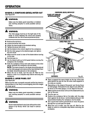
...in serious injury. LARGE PANEL CUT RIP FENCE Fig. 64 SUPPORTS Fig. 65 Place a support the same height as needed. Depending on the saw. Turn the saw off . If the panel is too ...you turn on the saw. Turn the saw on. Position the workpiece flat on the table with both hands on the miter gauge and feed the workpiece into the blade. Use a push ...the saw on the miter gauge lock knob and the hand farthest from the weight of the saw table behind the saw off . Note: The hand closest to the blade should be on the right side...
...in serious injury. LARGE PANEL CUT RIP FENCE Fig. 64 SUPPORTS Fig. 65 Place a support the same height as needed. Depending on the saw. Turn the saw off . If the panel is too ...you turn on the saw. Turn the saw on. Position the workpiece flat on the table with both hands on the miter gauge and feed the workpiece into the blade. Use a push ...the saw on the miter gauge lock knob and the hand farthest from the weight of the saw table behind the saw off . Note: The hand closest to the blade should be on the right side...
Owners Manual
Page 43
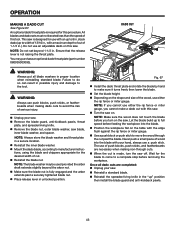
... be rated less than the speed of this procedure. Never push a small piece of wood into the blade. Position the workpiece flat on the table with the edge flush against the rip fence or miter gauge. Use a push block or push stick to make a dado cut with an up..., or featherboards when making dado cuts to a complete stop before you cannot make sure it turns freely then lower the blade. Set the blade height. Depending on the shape and size of the wood, use an adjustable dado on this saw. Turn the saw blade, inner blade washer...
... be rated less than the speed of this procedure. Never push a small piece of wood into the blade. Position the workpiece flat on the table with the edge flush against the rip fence or miter gauge. Use a push block or push stick to make a dado cut with an up..., or featherboards when making dado cuts to a complete stop before you cannot make sure it turns freely then lower the blade. Set the blade height. Depending on the shape and size of the wood, use an adjustable dado on this saw. Turn the saw blade, inner blade washer...
Owners Manual
Page 44
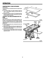
... larger workpieces. The finished height of the saw table. TO INSTALL THE TABLE EXTENSION ONTO THE RAILS See Figure 69. in . Securely clamp the boards to the end of the saw table, and to the saw with the rest of the saw table and extensions. The finished extension should ...that are holes in . There should be no space between the extension and the boards. There are 55-1/2 in the spreader bar. OPERATION CONSTRUCTING a TABLE EXTENSION See Figure 68. x 14-5/8 in. Assemble the pieces as shown. 14-5/8 in. 3/4 in. 1 in . The finished length and ...
... larger workpieces. The finished height of the saw table. TO INSTALL THE TABLE EXTENSION ONTO THE RAILS See Figure 69. in . Securely clamp the boards to the end of the saw table, and to the saw with the rest of the saw table and extensions. The finished extension should ...that are holes in . There should be no space between the extension and the boards. There are 55-1/2 in the spreader bar. OPERATION CONSTRUCTING a TABLE EXTENSION See Figure 68. x 14-5/8 in. Assemble the pieces as shown. 14-5/8 in. 3/4 in. 1 in . The finished length and ...


