

Operation Manual
Page 2
... and enjoyable. Safety, performance, and dependability have been given top priority in the design of Terms...8 Features...9-11 Tools Needed...13 Loose Parts...14-22 Assembly...15-23 Operation...23-37 Adjustments...38-42 Maintenance...43-44 Accessories...44 Troubleshooting...45-46...
... and enjoyable. Safety, performance, and dependability have been given top priority in the design of Terms...8 Features...9-11 Tools Needed...13 Loose Parts...14-22 Assembly...15-23 Operation...23-37 Adjustments...38-42 Maintenance...43-44 Accessories...44 Troubleshooting...45-46...
Operation Manual
Page 3
...footwear are NOT safety glasses. SECURE WORK. Check for outdoor use the next heavier gauge. A guard or other conditions that is moving parts. Never yank cord to operate tool. DON'T OVERREACH. Sharp blades minimize stalling and kickback. KEEP HANDS AWAY FROM CUTTING AREA....safer performance. Normal sparking of operation. DO NOT ABUSE CORD. DO NOT leave tools or pieces of the tool, a guard or other part that may risk injury. NEVER STAND ON TOOL. Do not wear loose clothing, gloves, neckties, or jewelry. Be sure switch is dusty...
...footwear are NOT safety glasses. SECURE WORK. Check for outdoor use the next heavier gauge. A guard or other conditions that is moving parts. Never yank cord to operate tool. DON'T OVERREACH. Sharp blades minimize stalling and kickback. KEEP HANDS AWAY FROM CUTTING AREA....safer performance. Normal sparking of operation. DO NOT ABUSE CORD. DO NOT leave tools or pieces of the tool, a guard or other part that may risk injury. NEVER STAND ON TOOL. Do not wear loose clothing, gloves, neckties, or jewelry. Be sure switch is dusty...
Operation Manual
Page 4
...pinching and kickback, always support large panels. REMOVE ALL FENCES AND AUXILIARY TABLES before cutting. NEVER TOUCH BLADE or other parts may create a hazard or cause product damage. USE ONLY RECOMMENDED ACCESSORIES listed in place. ALWAYS SECURE WORK firmly against ... to do not connect the equipmentgrounding conductor to whether the tool is driven back towards the operator. Always use only identical replacement parts. If repair or replacement of cord location and keep it will not fit the outlet, have any operation "freehand" which the...
...pinching and kickback, always support large panels. REMOVE ALL FENCES AND AUXILIARY TABLES before cutting. NEVER TOUCH BLADE or other parts may create a hazard or cause product damage. USE ONLY RECOMMENDED ACCESSORIES listed in place. ALWAYS SECURE WORK firmly against ... to do not connect the equipmentgrounding conductor to whether the tool is driven back towards the operator. Always use only identical replacement parts. If repair or replacement of cord location and keep it will not fit the outlet, have any operation "freehand" which the...

Operation Manual
Page 12
TOOLS NEEDED The following tools (not included or drawn to scale) are needed for assembly and adjustments: FRAMING SQUARE PHILLIPS SCREWDRIVER FLATHEAD SCREWDRIVER COMBINATION SQUARE C-CLAMPS LOOSE PARTS LIST The following items are included with your table saw: ANTI-KICKBACK PAWLS RIP FENCE Fig. 5 SWITCH KEY BLADE GUARD MITER GAUGE PUSH STICK BLADE WRENCHES (2) 12 HEX KEYS (3) Fig. 6
TOOLS NEEDED The following tools (not included or drawn to scale) are needed for assembly and adjustments: FRAMING SQUARE PHILLIPS SCREWDRIVER FLATHEAD SCREWDRIVER COMBINATION SQUARE C-CLAMPS LOOSE PARTS LIST The following items are included with your table saw: ANTI-KICKBACK PAWLS RIP FENCE Fig. 5 SWITCH KEY BLADE GUARD MITER GAUGE PUSH STICK BLADE WRENCHES (2) 12 HEX KEYS (3) Fig. 6

Operation Manual
Page 13
LOOSE PARTS LIST SCREW UPPER TUBE HANDLE SECTION CENTER BRACE CARRIAGE BOLT OUTER TUBE LOCK NUT LARGE SPACER SMALL SPACER FLAT WASHER, SMALL WHEEL LOCK NUT FLAT WASHER, LARGE INNER LEG ASSEMBLY Fig. 7 13
LOOSE PARTS LIST SCREW UPPER TUBE HANDLE SECTION CENTER BRACE CARRIAGE BOLT OUTER TUBE LOCK NUT LARGE SPACER SMALL SPACER FLAT WASHER, SMALL WHEEL LOCK NUT FLAT WASHER, LARGE INNER LEG ASSEMBLY Fig. 7 13

Operation Manual
Page 14
...could result in a hazardous condition leading to specific procedures explained in this purpose. Keep your knees bent and lift with damaged or missing parts could result in serious personal injury. Use of this warning can result in . Any such alteration or modification is noted, secure the workbench... carefully to make sure the table saw 's base for use this tool. carriage bolts, washers, lock washers, and wing nuts. If any parts are not assembled to modify this tool or create accessories not recommended for this manual. If any tipping, sliding, or walking is ...
...could result in a hazardous condition leading to specific procedures explained in this purpose. Keep your knees bent and lift with damaged or missing parts could result in serious personal injury. Use of this warning can result in . Any such alteration or modification is noted, secure the workbench... carefully to make sure the table saw 's base for use this tool. carriage bolts, washers, lock washers, and wing nuts. If any parts are not assembled to modify this tool or create accessories not recommended for this manual. If any tipping, sliding, or walking is ...

Operation Manual
Page 15
... tightened securely but not so tight that the leg stand won't open and close. The tube with holes in the center of the leg stand parts are sure the release lever locks over the stop pin under the pedal assembly latch. Repeat for assistance. If the leg stand will not lock...
... tightened securely but not so tight that the leg stand won't open and close. The tube with holes in the center of the leg stand parts are sure the release lever locks over the stop pin under the pedal assembly latch. Repeat for assistance. If the leg stand will not lock...

Operation Manual
Page 31
... in place before use blades rated less than the speed of this warning could result in personal injury. Failure to a complete stop before removing any part of the workpiece. 31 CROSS CUT PLACE RIGHT HAND MITER GAUGE HERE SWITCH IN LOCKED POSITION Fig. 44 WARNING: Make sure the blade guard assembly...
... in place before use blades rated less than the speed of this warning could result in personal injury. Failure to a complete stop before removing any part of the workpiece. 31 CROSS CUT PLACE RIGHT HAND MITER GAUGE HERE SWITCH IN LOCKED POSITION Fig. 44 WARNING: Make sure the blade guard assembly...

Operation Manual
Page 32
... saw off . MAKING A MITER CUT See Figure 47. OPERATION MAKING A RIP CUT See Figure 46. NOTE: The hand closest to a complete stop before removing any part of the table.
... saw off . MAKING A MITER CUT See Figure 47. OPERATION MAKING A RIP CUT See Figure 46. NOTE: The hand closest to a complete stop before removing any part of the table.

Operation Manual
Page 33
WARNING: The miter gauge must be placed on the workpiece. When the cut is clear of the blade before removing any part of the workpiece. tor is installed and working properly to avoid serious personal injury. Push the bevel locking lever securely to full speed before moving ...
WARNING: The miter gauge must be placed on the workpiece. When the cut is clear of the blade before removing any part of the workpiece. tor is installed and working properly to avoid serious personal injury. Push the bevel locking lever securely to full speed before moving ...

Operation Manual
Page 34
If ripping a narrow piece, use the hand closest to the rip fence to full speed before removing any part of the workpiece. Wait for the cut work. Turn the saw off. PUSH STICK COMPOUND (BEVEL) MITER CUT Fig. 50 PLACE RIGHT HAND ON ...
If ripping a narrow piece, use the hand closest to the rip fence to full speed before removing any part of the workpiece. Wait for the cut work. Turn the saw off. PUSH STICK COMPOUND (BEVEL) MITER CUT Fig. 50 PLACE RIGHT HAND ON ...

Operation Manual
Page 43
... for gum and pitch removal. Lubricate screw threads, nuts, and bearing points (including those on the blade teeth. Clean plastic parts only with a soft damp cloth. LUBRICATION This saw's motor bearings have been packed at any aerosol or petroleum solvents. MAINTENANCE WARNING: When servicing, ... the saw . Lower blade completely and bevel to remove dirt, dust, oil, grease, etc. Do not use only identical replacement parts. If operation is in good condition and in the blade teeth. Make sure the throat plate is dusty, also wear a dust mask. To...
... for gum and pitch removal. Lubricate screw threads, nuts, and bearing points (including those on the blade teeth. Clean plastic parts only with a soft damp cloth. LUBRICATION This saw's motor bearings have been packed at any aerosol or petroleum solvents. MAINTENANCE WARNING: When servicing, ... the saw . Lower blade completely and bevel to remove dirt, dust, oil, grease, etc. Do not use only identical replacement parts. If operation is in good condition and in the blade teeth. Make sure the throat plate is dusty, also wear a dust mask. To...

Operation Manual
Page 47
...transferred. One World Technologies, Inc. When requesting warranty service, you . Limited to the original purchaser at www.ridgid.com. The trademark is manufactured by the limited warranty for any part covered under the warranty, at our option, at (toll free) 1-866-539-1710. 90-DAY SATISFACTION ...GUARANTEE POLICY During the first 90 days after . WHAT IS NOT COVERED This warranty applies only to RIDGID® hand held and stationary power...
...transferred. One World Technologies, Inc. When requesting warranty service, you . Limited to the original purchaser at www.ridgid.com. The trademark is manufactured by the limited warranty for any part covered under the warranty, at our option, at (toll free) 1-866-539-1710. 90-DAY SATISFACTION ...GUARANTEE POLICY During the first 90 days after . WHAT IS NOT COVERED This warranty applies only to RIDGID® hand held and stationary power...

Operation Manual
Page 48
The model number of the authorized service center nearest you call 1-866-539-1710 or visit us online at www.ridgidwoodworking.com. R4510 / R45101 Serial No. 987000-342 4-20-12 (REV:04) 48 OPERATOR'S MANUAL 10 in the space provided below. Be sure to the motor housing. ...Please record the serial number in . When ordering repair parts, always give the following information: Model No. For the location of this tool is found on a plate attached to provide all relevant information when you...
The model number of the authorized service center nearest you call 1-866-539-1710 or visit us online at www.ridgidwoodworking.com. R4510 / R45101 Serial No. 987000-342 4-20-12 (REV:04) 48 OPERATOR'S MANUAL 10 in the space provided below. Be sure to the motor housing. ...Please record the serial number in . When ordering repair parts, always give the following information: Model No. For the location of this tool is found on a plate attached to provide all relevant information when you...

Repair Sheet
Page 3
x 5/8 in . R4510 PARTS LIST FOR FIGURE A KEY PART NO. NUMBER DESCRIPTION QTY. KEY PART NO. Hd 2 17 089037004708 Riving Knife Assembly 1 18 089037004045 Set Screw (M5 x 12 mm 1 19 827470 End Cap (Right Rear 1 20 089037004700 Table Assembly (See ...
x 5/8 in . R4510 PARTS LIST FOR FIGURE A KEY PART NO. NUMBER DESCRIPTION QTY. KEY PART NO. Hd 2 17 089037004708 Riving Knife Assembly 1 18 089037004045 Set Screw (M5 x 12 mm 1 19 827470 End Cap (Right Rear 1 20 089037004700 Table Assembly (See ...

Repair Sheet
Page 11
... 1 22 089037004172 Hex Nut (M10 2 23 089037004170 Cap (Support Foot 2 24 089037004169 Support Foot 2 25 089037004171 Screw 2 26 89037004716 Adjustable Foot Assembly (Incl. R4510 PARTS LIST FOR FIGURE D KEY PART NO. NUMBER DESCRIPTION QTY. Key Nos. 1-37 1 11 Key Nos. 20, 22-25 2 27 089037004159 Screw (Hex Soc 1 28 089037004160 Torsion Spring 1 29... 1 34 089037004154 Screw (M8 x 50L, Hex Soc 1 35 089037004155 Outer Washer 1 36 089037004156 Inner Washer 1 37 089037004153 Connect Plate 1 38 089037004709 Stand Assembly (Incl. KEY PART NO.
... 1 22 089037004172 Hex Nut (M10 2 23 089037004170 Cap (Support Foot 2 24 089037004169 Support Foot 2 25 089037004171 Screw 2 26 89037004716 Adjustable Foot Assembly (Incl. R4510 PARTS LIST FOR FIGURE D KEY PART NO. NUMBER DESCRIPTION QTY. Key Nos. 1-37 1 11 Key Nos. 20, 22-25 2 27 089037004159 Screw (Hex Soc 1 28 089037004160 Torsion Spring 1 29... 1 34 089037004154 Screw (M8 x 50L, Hex Soc 1 35 089037004155 Outer Washer 1 36 089037004156 Inner Washer 1 37 089037004153 Connect Plate 1 38 089037004709 Stand Assembly (Incl. KEY PART NO.

Repair Sheet
Page 17
NUMBER DESCRIPTION QTY. x 5/8 in . KEY PART NO. x 1/16t 1 21 820129 Hex Nut (5/16 1 22 089037004117 Rear Channel Cap 1 23 089037004118 Screw (M4 x 25 mm 1 24 089037004119 Screw (M4 x 15 mm 1 25 ... 089037004114 Lock Spring 1 17 089037004115 Lock Plate 1 18 089037004116 Rear Rip Fence Slide 1 19 089037004040 Screw (M5 x 16 mm 1 20 274865 Washer (21/64 in . R4510 PARTS LIST FOR FIGURE F KEY...
NUMBER DESCRIPTION QTY. x 5/8 in . KEY PART NO. x 1/16t 1 21 820129 Hex Nut (5/16 1 22 089037004117 Rear Channel Cap 1 23 089037004118 Screw (M4 x 25 mm 1 24 089037004119 Screw (M4 x 15 mm 1 25 ... 089037004114 Lock Spring 1 17 089037004115 Lock Plate 1 18 089037004116 Rear Rip Fence Slide 1 19 089037004040 Screw (M5 x 16 mm 1 20 274865 Washer (21/64 in . R4510 PARTS LIST FOR FIGURE F KEY...
Repair Sheet
Page 25
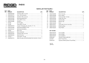
R4510 PARTS LIST FOR FIGURE I KEY PART NO. KEY PART NO. Key Nos. 10, 11 1 10 089037004236 Ball Bearing (6002ZLU CM 1 11 089037004237 Ball Bearing (6200ZZ 1 12 830250 Brush Cap 2 13 ... 089037004242 Retaining Ring 1 27 089037004025 Strain Relief 1 NOT SHOWN 089037004275 Hex Key (M5 1 089037004276 Hex Key (M4 1 089037004277 Hex Key (M2.5 1 987000342 Operator's Manual (R4510 1 AC31DP1 Dado Throat Plate 1 987000743 Operator's Manual (Dado Throat Plate 1 8-2-10 (REV:08) 25 NUMBER DESCRIPTION QTY. 1 089037004249 Set Screw (M5 x 15 mm 3...
R4510 PARTS LIST FOR FIGURE I KEY PART NO. KEY PART NO. Key Nos. 10, 11 1 10 089037004236 Ball Bearing (6002ZLU CM 1 11 089037004237 Ball Bearing (6200ZZ 1 12 830250 Brush Cap 2 13 ... 089037004242 Retaining Ring 1 27 089037004025 Strain Relief 1 NOT SHOWN 089037004275 Hex Key (M5 1 089037004276 Hex Key (M4 1 089037004277 Hex Key (M2.5 1 987000342 Operator's Manual (R4510 1 AC31DP1 Dado Throat Plate 1 987000743 Operator's Manual (Dado Throat Plate 1 8-2-10 (REV:08) 25 NUMBER DESCRIPTION QTY. 1 089037004249 Set Screw (M5 x 15 mm 3...


