Owners Manual
Page 2
...; Introduction...2 General Safety Rules...3-4 Specific Safety Rules...5 Symbols...6 Electrical...7-8 Features...9-10 Tools Needed...10 Loose Parts...11 Assembly...12-20 Operation...21-25 Adjustments...26-27 Maintenance...27-28 Warranty...29 Parts Ordering and Service...Back page INTRODUCTION...
...; Introduction...2 General Safety Rules...3-4 Specific Safety Rules...5 Symbols...6 Electrical...7-8 Features...9-10 Tools Needed...10 Loose Parts...11 Assembly...12-20 Operation...21-25 Adjustments...26-27 Maintenance...27-28 Warranty...29 Parts Ordering and Service...Back page INTRODUCTION...
Owners Manual
Page 10
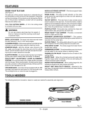
... need for accurate cuts. TOOLS NEEDED The following tools (not included or drawn to -read indicator on the miter guide shows the exact angle for assembly and alignment: FRAMING SQUARE 10 - tile cutting wheel is inoperable. MICRO-CUT FENCE SUPPORT - The easy-to scale) are attempting. To lock the switch, install...
... need for accurate cuts. TOOLS NEEDED The following tools (not included or drawn to -read indicator on the miter guide shows the exact angle for assembly and alignment: FRAMING SQUARE 10 - tile cutting wheel is inoperable. MICRO-CUT FENCE SUPPORT - The easy-to scale) are attempting. To lock the switch, install...
Owners Manual
Page 11
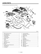
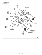
...Cap bolt (short 2 E - Lock nut 1 L - Water tray extensions 2 M - Wheel 2 O - Spacer 8 X - Hex head bolt 2 AA - Hose clamps 12 11 - Motor head assembly 1 D - Sleeve 2 I HH GG FF EE DD CC U J l K X Y V W AA BB L C E F D HG m o n p q z r t S ii Fig. 5 A...1 HH - Tile cutting wheel 1 C - Long clear tube 1 F - Long tube assembly 1 T - Carrage bolt 8 Z - Span-deck clamp 1 FF - Sliding table extension 1 II - Center brace 1 DD - Water tray frame assembly 1 B - Short cap screw 4 K - Left outer tube 1 V - Wheel wrench...
...Cap bolt (short 2 E - Lock nut 1 L - Water tray extensions 2 M - Wheel 2 O - Spacer 8 X - Hex head bolt 2 AA - Hose clamps 12 11 - Motor head assembly 1 D - Sleeve 2 I HH GG FF EE DD CC U J l K X Y V W AA BB L C E F D HG m o n p q z r t S ii Fig. 5 A...1 HH - Tile cutting wheel 1 C - Long clear tube 1 F - Long tube assembly 1 T - Carrage bolt 8 Z - Span-deck clamp 1 FF - Sliding table extension 1 II - Center brace 1 DD - Water tray frame assembly 1 B - Short cap screw 4 K - Left outer tube 1 V - Wheel wrench...

Owners Manual
Page 12
... securely but not so tight that may have carefully inspected and satisfactorily operated the tool. The saw from the axles on the bolt. ASSEMBLING THE WSUV™ Wet Saw Utility Vehicle / leg stand See Figure 6. All hardware must be placed on the right outer tube (G) and into... the inner leg assembly (G) and secure in place using lock nut. Repeat with the second wheel. Failure to comply could result in accidental starting and possible serious...
... securely but not so tight that may have carefully inspected and satisfactorily operated the tool. The saw from the axles on the bolt. ASSEMBLING THE WSUV™ Wet Saw Utility Vehicle / leg stand See Figure 6. All hardware must be placed on the right outer tube (G) and into... the inner leg assembly (G) and secure in place using lock nut. Repeat with the second wheel. Failure to comply could result in accidental starting and possible serious...
Owners Manual
Page 13
English ASSEMBLY LOCK NUT RIGHT OUTER TUBE LEFT UPPER TUBE SPACER LOWER BRACE Carriage bolt RIGHT UPPER TUBE HEX HEAD BOLT LEFT OUTER TUBE STOP PIN WHEEL lock NUT CENTER BRACE INNER LEG ASSEMBLY AXLE FLAT WASHER, large FLAT WASHER, small Fig. 6 13 -
English ASSEMBLY LOCK NUT RIGHT OUTER TUBE LEFT UPPER TUBE SPACER LOWER BRACE Carriage bolt RIGHT UPPER TUBE HEX HEAD BOLT LEFT OUTER TUBE STOP PIN WHEEL lock NUT CENTER BRACE INNER LEG ASSEMBLY AXLE FLAT WASHER, large FLAT WASHER, small Fig. 6 13 -
Owners Manual
Page 14
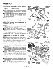
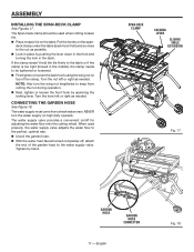
... tank on the lower brace of the leg stand and push the tank firmly against the center brace until the slot in the motor head assembly with the holes on top of the leg stand. Holding the diverter valve, connect the long clear tube (with the cleaning nozzle) to the... cap bolts using the tube clips on the side of the water tray frame. Insert short cap bolts. Insert into sleeve. ASSEMBLY Installing the water tray frame assembly to the leg stand See Figure 7. Lock the table stop by-pass by pulling up on the stop by-pass Leg stand...
... tank on the lower brace of the leg stand and push the tank firmly against the center brace until the slot in the motor head assembly with the holes on top of the leg stand. Holding the diverter valve, connect the long clear tube (with the cleaning nozzle) to the... cap bolts using the tube clips on the side of the water tray frame. Insert short cap bolts. Insert into sleeve. ASSEMBLY Installing the water tray frame assembly to the leg stand See Figure 7. Lock the table stop by-pass by pulling up on the stop by-pass Leg stand...
Owners Manual
Page 15
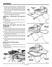
... water tray (drain plug end to the submersible water pump and set the pump in the bottom of the water tank. ASSEMBLY Push the short clear tube of the T-connector assembly over cord connections to the front of the water frame. Slide the particle trap out of (or into the...
... water tray (drain plug end to the submersible water pump and set the pump in the bottom of the water tank. ASSEMBLY Push the short clear tube of the T-connector assembly over cord connections to the front of the water frame. Slide the particle trap out of (or into the...
Owners Manual
Page 16
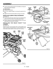
.... installing sliding table extension See Figure 15. From the side of the saw . installing THE ready rack™ tile carrier See Figure 16. English ASSEMBLY Lock the miter guide securely to the table by turning the table extension lock knob underneath the extension clockwise. Lock knob Miter guide Miter...
.... installing sliding table extension See Figure 15. From the side of the saw . installing THE ready rack™ tile carrier See Figure 16. English ASSEMBLY Lock the miter guide securely to the table by turning the table extension lock knob underneath the extension clockwise. Lock knob Miter guide Miter...
Owners Manual
Page 17
ASSEMBLY installing THE span-deck clamp See Figures 17. The water supply valve provides a convenient on high (fully opened). deck clamp under the table (back hook ...
ASSEMBLY installing THE span-deck clamp See Figures 17. The water supply valve provides a convenient on high (fully opened). deck clamp under the table (back hook ...
Owners Manual
Page 18
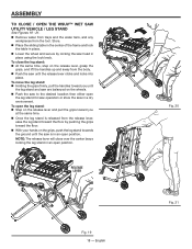
... you at the same time. Once the leg stand is in an open position. 14 13 12 11 10 9 8 Release lever Fig. 19 18 - ASSEMBLY TO CLOSE / open position.
... you at the same time. Once the leg stand is in an open position. 14 13 12 11 10 9 8 Release lever Fig. 19 18 - ASSEMBLY TO CLOSE / open position.

Owners Manual
Page 19
... the spindle. Spindle lock To tighten To loosen Wheel wrench Wheel guard lock Spindle Fig. 22 Wheel nut Inner washer Outer washer Fig. 23 19 - ASSEMBLY tile cutting wheel For maximum performance and safety, it is recommended that you are available at your saw. WARNING: To prevent possible electrical hazards...
... the spindle. Spindle lock To tighten To loosen Wheel wrench Wheel guard lock Spindle Fig. 22 Wheel nut Inner washer Outer washer Fig. 23 19 - ASSEMBLY tile cutting wheel For maximum performance and safety, it is recommended that you are available at your saw. WARNING: To prevent possible electrical hazards...
Owners Manual
Page 20
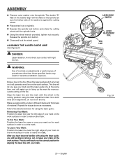
... correct position for using the laser guide: Removing Your Mark: Position the laser line near the right edge of your mark on the work surface. ASSEMBLY Place an outer washer onto the spindle. Practice will teach you will assist you in hazardous radiation exposure. To Leave Your Mark: Position the...
... correct position for using the laser guide: Removing Your Mark: Position the laser line near the right edge of your mark on the work surface. ASSEMBLY Place an outer washer onto the spindle. Practice will teach you will assist you in hazardous radiation exposure. To Leave Your Mark: Position the...
Owners Manual
Page 28
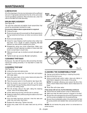
...Remove brush cap with a sufficient amount of high grade lubricant for the life of the unit under normal operating conditions. Brush cap Brush assembly Brush assembly Brush cap Fig. 39 Cleaning the rails During use, the rails will not run the clean water through the saw and water pump...pulling the table to clean the rails often. English Do not replace one side without replacing the other. Reassemble using new brush assemblies. Tighten securely. Empty dirty water from sliding smoothly. NOTE: Do not handle the pump while it is oriented correctly (straight) ...
...Remove brush cap with a sufficient amount of high grade lubricant for the life of the unit under normal operating conditions. Brush cap Brush assembly Brush assembly Brush cap Fig. 39 Cleaning the rails During use, the rails will not run the clean water through the saw and water pump...pulling the table to clean the rails often. English Do not replace one side without replacing the other. Reassemble using new brush assemblies. Tighten securely. Empty dirty water from sliding smoothly. NOTE: Do not handle the pump while it is oriented correctly (straight) ...

